Download
1 / 15
210 likes | 560 Views
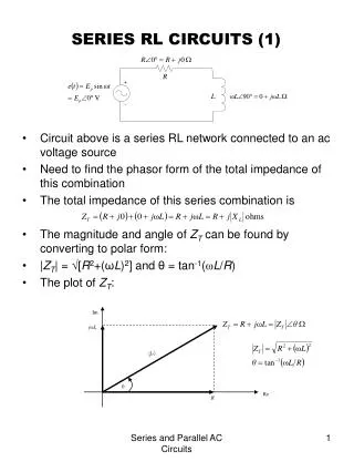
RL and LC Circuits. Capacitor and Inductors in Series Resistors and Inductors in Series. RL Circuits. As the switch is thrown closed in an RL circuit, the current in the circuit begins to increase and a back EMF that opposes the increasing current is induced in the inductor.

E N D
RL and LC Circuits Capacitor and Inductors in Series Resistors and Inductors in Series
RL Circuits • As the switch is thrown closed in an RL circuit, the current in the circuit begins to increase and a back EMF that opposes the increasing current is induced in the inductor. • The back EMF is εL = -L(dI/dt) • Because the current is increasing dI/dt is positive.
RL Circuits • The EMF across the inductor is negative which reflects the decrease in electric potential that occurs in going across the inductor.
RL Circuits • After the switch is closed there is a large back EMF that opposes current flow • EMF –L(dI/dt) • So not much current flows • I = εo/R • Using Kirchoff’s loop rule we find • εo –I/R - L(dI/dt)=0
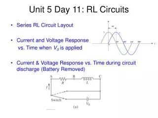
RL Circuits • The current does not increase instantly, but increases as an RC circuit does. • It increases to its final equilibrium value when the switch is closed but instead increases according to an exponential function. • I(t) = (εo/R)(1-e-t/τ) • Where τ = L/R
RL Circuits • Once current is flowing it is hard to stop • Current decays • I = Ioe-t/τ • I = (εo/R) e-t/τ
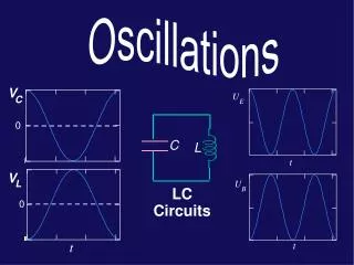
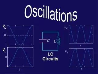
LC Circuits • If the capacitor is initially charged and the switch is then closed, both the current in the circuit and the charge on the capacitor oscillate between maximum positive and negative values. • When the capacitor is fully charged, the energy U in the circuit is stored in the electric field of the capacitor and is • Qmax2 /2C
LC Circuits • When the switch in the circuit is thrown then the capacitor discharges, this is providing a current in the circuit and the energy stored in the electric field of the capacitor now becomes stored in the magnetic field of the inductor • When the capacitor is fully discharged, it stores no energy. At this time the current reaches its maximum value and all the energy is stored in the inductor.
LC Circuits • The current continues in the same direction, decreasing in magnitude, with the capacitor becoming fully charged again but with the polarity of its plates now opposite its initial polarity. This is followed by another discharge until the circuit returns to its original state of maximum charge Qmax.
LC Circuits • The capacitor initially carries a charge Qo. • When the switch is closed: • -L dI/dt = Q/C • L (d2Q/dt2) + Q/C = 0 • Where I = dQ/dt
Charge and Current in LC Circuits • I = ωQo • ω is the angular frequency • Q(t) = Qo cos ωt • I(t) = ωQo sin ωt • ω = 1/√(LC)
Current Oscillations • The current oscillates periodically and the stored energy is • U = ½ Q2/C + ½ LI2 = a constant • This is the total energy in an LC circuit