Download
1 / 37
370 likes | 552 Views
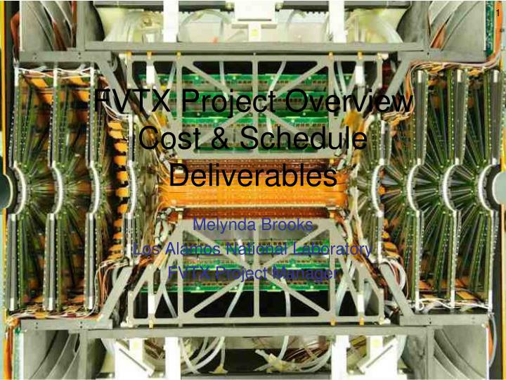
FVTX Project Overview Cost & Schedule Deliverables. Melynda Brooks Los Alamos National Laboratory FVTX Project Manager. Talk Outline, Day ’ s Agenda. Coming Talks: Transition to Operations - Ed Commissioning – Eric + Jin Software Analysis - Xiaorong. This talk: Project Status Overview

E N D
FVTX Project OverviewCost & ScheduleDeliverables Melynda Brooks Los Alamos National Laboratory FVTX Project Manager
Talk Outline, Day’s Agenda • Coming Talks: • Transition to Operations - Ed • Commissioning – Eric + Jin • Software Analysis - Xiaorong This talk: • Project Status Overview • Cost & Schedule • Project Deliverables • Near Future Work
FVTX Geometrical Design • Four tracking stations with full azimuthal coverage • 75 m pitch strips in radial direction, 3.75° staggered phi strips • Radiation length < 2.4%/wedge to minimize multiple scattering • Outer Support and Cooling outside active area • Kapton cable plant primarily outside active area Backplane HDI Cage Sensor FPHX Chips Half Disk
FVTX Electrical Design • p on n ministrip sensor, 75 m x 3.75º • Data push FPHX readout chip • High density interconnect cable • ROC (big wheel area in IR) • FEM (VME crate in CH) • PHENIX DCMs HDI ROC, IR sensor FEM, Counting House FPHX
FY10 Progress – Where we were last review HDIs • Wedge Components • All sensors procured and tested. ~100% yield • 24 FPHX wafers procured and 17 tested, >95% yield • All small HDIs received (125), 25 large HDIs received, rest in progress, ~100% yield • All backplanes received and within specifications • Detector Assembly • 120(118) small production wedges with chips (chips+sensors) and 23 large production wedges assembled at SiDet • Disk assembly at BNL underway, cage assembly plan in place • DAQ • FEM Interface 1st article tested good, rest in assembly • FEM production board 1st article received and tests good • Full ROC prototype underway. • Mechanics • Disk, cage fabrication in progress • Assembly fixtures for disk, cage completed FPHX Wafer Wedge edge ROC, FEM, FEM Interface
FY11 Now • Wedge Assembly • All HDIs tested and delivered, perform very well – UNM-led effort • 96 + 10 spare small, 288 + 25 large wedges assembled • Effort led by Columbia University & FNAL to assemble wedges, assemble test stand, and test all wedges at each stage. Spanning more than 1 year’s time • Disk, Cage, Big Wheel Assembly • All disks, cages, big wheels assembled • Assembly Effort led by NMSU with significant student/post-doc participation. Significant manpower from our Czech collaborators. • Additional thanks to all the collaborators who came to BNL to help out • UNM-led design and testing of extension cables, forming of 768 HDI and extension cables FPHX Wafer
FY11 Now • DAQ - LANL/UNM-led design and testing, extensive work by Sergey on FPGA coding across the systems • FEM Interface production boards (4 + 2 spare) received and tested • FEM production boards (48 + 4 spare) received and tested • ROC design completed and production boards (24 + 4) received and tested • DCM IIs delivered and working well (Nevis) • Commissioning with PHENIX DAQ • successful • Mechanics - LANL/BNL/LBNL/HYTEC • Disk, cage fabrication completed, surveyed, leak and pressure checked • Assembly fixtures for disk, cage worked well • Support Systems – LANL/BNL/Nevis • Power distribution, interlocks, DCMs all delivered FPHX Wafer edge 6 ROCs
FVTX Installation • Thanks to tremendous help from BNL support staff: • FVTX integrated with VTX and installed into IR in December 2011 • Significant cabling plant installed and connected to detector, completed January 2012 • All support services (power, interlocks, cooling) installed except for 4 data fibers which had interference with support structure member
FVTX Commissioning – see details in Eric’s and Jin’s talksFVTX Operational Status - now
FVTX Operation • Jan 13: Detector installed and readout started, detector in retracted position • Jan. 13 – Feb 8:Power up and check out of detector– most of detector operational • Feb 9 : FVTX/VTX detectors moved from retracted position to closed position around the beam-pipe. Few new problems occurred: • SE5 ROC on East side shorted out to big wheel on West side. • Few ROCs in NW started showing higher level noise and issues with running calibration • SW5 stopped working (damaged SC fiber transceiver) • Mar 13: Open up, check cooling, etc. at end of 200 GeV p-p run • Readout seems good after electronics work, retraction, cooling seems o.k. – radiation effects • Mar 20: Close back up,510 GeV p+p running started, Detector Operational • March 28 – Access, changed some grounding - NW cage noise gone. Everything functioning except SE5, SW5. ROCs overlap Al cooling plate when detector closed
FVTX Operation • Functional wedges – 100% of wedges that are on ROCs with SC communication respond to download-readback. 8/8448 chips were known to be non-functional when we assembled the detector.99.9% of chips are functional • ROC Status • One ROC (SW5) - has FO transmitter damaged – 1/24 = 4% of detector • One ROC (SE5) lost 1 data fiber when shorted to west side, after second close-up whole ROC works intermittently – 1-4% of detector • 2 ROCs have 1 fiber which cannot be plugged in - 2% of detector • Will remove and repair above ROCs during shutdown. Support member will be modified • FEM/DCM Status - FEMs, DCMs, all currently functioning • Collecting Physics data in PHENIX Big Partition Radiographs from clusters Radiographs from reconstructed tracks South Arm North Arm
However… • Some operational parts of the detector do still have some stability issues to address: • Some ROCs do not synchronize wedges and FEMs every run – Issue with START delivery to ROC? Hope to address with more robust cable, possibly better clock distribution board design… • Some wedges/chips can temporarily fall out of data collection for a particular run – since wedges are shown to be fully functional either the fiber latch is lost or the synchronization of the wedge is not achieved at startup need to determine what causes the loss • Some wedges off due to high current draw at one point – need to investigate • Additional work during/after run to make system readout more robust
FVTX Data Collected • 200 GeV p+p running, retracted position (13-Jan-12 – 8-Feb-12) • Data collected, but cannot be analyzed for Physics • 200 GeV p+p running, closed position (9-Feb-12 to 12-Mar-12) • ~100M triggers collected, but only powered on 1/6 of ROCs at a time. • 200 GeV to 510 GeV shutdown (~14-Mar-12) • Determined cooling system was operating as expected. Increased current draw was from radiation damage. Detector operates fine with increased current limits on bias voltage. • Readout worked fine after working on problematic ROCs from above • 510 GeV running (~20-Mar-12 – 19-Apr-12) • 20-Mar to 28-Mar – most of the detector on but 5/6 of one cage showed significantly more noise • 28-Mar grounding issues with one cage solved. All ROCs operational except two, 2 data fibers which could not be plugged in. • FVTX Became “Operational” • Cu-Au, U-U running • Continued FVTX operations
Cost & Schedule Executive Summary • FVTX Cost Roll-Up: • Management Plan Cost = $4880k, Contingency = $927k (23%) • Actual Costs = $4803k • Remaining contingency = $77k • FVTX Schedule Summary • Last HDIs delivered in June, 2011, allowing wedge assembly to complete • Last extension cables delivered in August, 2011 • Last ROC delivered to BNL beginning of November, 2011 • Disk, cage, big wheel assembly completed November 2011 • Integration with VTX and installation into 1008 completed December 2011 • Cabling completed and commissioning started in earnest in January 2012 • Very compressed schedule in the last few months – FVTX collaborators worked extremely hard to still meet our Project Complete deadlines. • Pre-testing of components resulted in few hardware failures during this period
FVTX Project Cost Summary • Primary overruns – items with higher manufacturing complexity than anticipated: • HDI (small pitch) • Extension Cables (small pitch) • ROC (# lineslarge number of board layers, small trace widths) • Carbon composite components • Savings in items which had been done before: • Sensors • FPHX chip (based on FPIX chip) • FNAL assembly • FEM boards (complexity not high) (Baseline Cost + contingency) – (Actual Cost)
Schedule Summary • Delays came primarily from same items which caused cost increases: • Backplanes • HDIs • Extension Cables • ROCs
FVTX Project Deliverables All components delivered except 2 FEMs – we plan to order more spares with contingency
FVTX Functional Requirements • All functional requirements met • Measurements of deliverables will be described in coming slides
Mini-strips Active • Functional Wedges/Chips: • Out of 384 wedges, in the system, we are able to establish communication with all 384 wedges when the slow control fibers were working. From the detector assembly we know that of the 8448 chips in the system, 8 of them were not operational. This leaves 99.9% of the wedge channels functional. • Functional ROCs/FEMS wedges read out fully • One ROC (SW5) - has FO transmitter damaged – 4% of detector • One ROC (SE5) lost 1 data fiber when shorted to west side, after second close-up whole ROC works intermittently – 1-4% of detector • 2 ROCs have 1 fiber which cannot be plugged in - 2% of detector • This leaves 90% of the detector able to be read out • 80% of detector active requirement is met • “Optimal performance” should be met when we fix ROCs, address stability
Hit Efficiency • Intrinsic wedge hit efficiency • Project station 0,1,3 tracks to station 2 in fully functional area • Count number of station 2 hits - >95% found • Efficiency across the entire detector • Project all station 0,1,3 tracks to station 2 and • count hits • >90% efficiency in all areas that are ON • 85% detector efficiency requirement is met • “Optimal Performance” also met in active • areas of detector Limited r range ROC OFF, Fiber unplugged ROC OFF Reconstructed Coordinate r vs. z (cm)
Detector Resolution x x x x • Extracting Intrinsic Detector Resolution • Intrinsic resolution should be ≤ 75 mm/√12 = 22 mm • Take station 1,3 hits and project to station 2. Measure difference between projected position and measured position = “residual”. • Projection error, multiple scattering error, detector alignment in residual • Require that station 0-1-3 residual be <100 mm to try to reduce multiple scattering contributions • Require station 1,2,3 all fall in the same wedge to reduce alignment contributions • Compare real data residual to simulated residual with muons of p=(0.5, 2.0) GeV to see if extracted residual is of same order (assume we are dominated by low p) • Simulated and real data are approximately the same Intrinsic detector resolution matches simulation (<25 mm) This is also our “Optimal Performance”
Noise Hits • Noise measured with our calibration system • Our specification is to have ~500 electrons noise • Integrated over a large fraction of the detector, we get mean value of 429 e • Absolute hit rate in p-p running • Specification is < (3.5 hits)/(26chips*128channels) = 0.1% hits/chip-channel. • In real p-p running we achieve <0.8 hits/wedge • <0.1% noise hit rate requirement is met • This is also our “Optimal Performance” 429 e noise 2500 e thresh
DAQ Requirements • Latency: • We wanted hits to be sent out from detector as fast as possible in case we might want to participate in a trigger some time in the future • By design, FPHX outputs 4 hits/ beam crossings (= 400 ns) which is sufficient to meet our requirements of latency < 4 ms. • Multi-event Buffering • PHENIX requires that we be able to buffer up to 4 events so that we can handle adjacent beam-bucket triggers • FPGA code has been designed to buffer these 4 events • Readout Time, Readout Rate • The readout time for the FEM FPGA code has been fully simulated and is shown to take a maximum of 9 msfor an event that has the maximum number of hits that can be accepted. This meets our specification of <40 ms readout time. • The FEM FPGA code has been fully simulated and is able to sustain a trigger rate of 5 MHz when empty packets are generated • in the worst possible case where there are 720*4 hits in every packet generated (a hit rate we never expect to achieve), a sustained rate to the DCM of 27 kHz can still be achieved. Both of these are >our specification of 10 kHz
Contingency • We had ~$77k in contingency left in the project, some of which was already transferred to operations when remaining wedge assembly funds were returned by FNAL to BNL. We plan to purchase spare parts: • Spare FEMs – quote for ~$20k/6 boards • Spare ROC boards – quote for ~$15k/board • Clock Distribution boards - ~$4k/set • LV front panels - ~$5k • Total = ($29k * burden) + $15k * (# ROC boards) * burden
Summary • Project Status • Large fraction of system components are functional and collecting data • However, we do have some work to do to get system closer to 100% stability from run-to-run • Cost & Schedule • Project completed within budget • Project completed within December 30, 2011 Project Complete date (revised) • Deliverables • All detector performance specifications met • All components delivered except some spare FEM boards which we will order. • Future • Analyze data from 510 GeV p+p run, coming heavy ion run. 200 GeV p+p run will probably only be able to be used to check intrinsic performance. • Shutdown work to fix damaged ROCs, any other issues • Access and shutdown work to improve data collection performance
ARRA FVTX Funds, Milestones • $2M in ARRA funds received in summer 2009. Milestones: • Plan Actual • Initiate Backplane procurement process 6/2009 6/2009 • Initiate Cage procurement process 6/2009 6/2009 • Start Recovery Act FVTX Management and Integration by LANL 7/2009 7/2009 • Initiate Ancillary System procurement process 11/2009 11/2009 • Review and approve ROC/FEM design 12/2009 12/2010 • Initiate ROC/FEM production procurement process 1/2010 3/2010 • Begin testing ROC/FEM board 2/2010 9/2010 • Begin attaching HDIs to Backplane 3/2010 5/2010 • Begin testing production version of FPHX chips 4/2010 4/2010 • Begin attaching chips to HDIs 6/2010 6/2010 • Begin attaching sensors to HDIs 7/2010 6/2010 • Begin testing wedge assemblies 8/2010 6/2010 • Begin assembling wedges into disks 9/2010 11/2010
Reminder of Simulated Performance • Improved S:B in heavy flavor via single muons allows precision heavy flavor RAA, ALL measurements • (Updated Information in Simulation Talk) 200 GeV/c 500 GeV/c Simulated Shown for Two Different E-Loss models
Cabling D. Fields UNM Wedge D. Winter Columbia HDI M. Hoferkamp UNM, Columbia Wedge Assembly D. Winter/SiDet Columbia, NMSU, UNM Flex Cable D. Fields UNM Wire Bond D. Winter/SiDet Columbia Fibers D. Fields UNM Wedge QA D. Winter/SiDet Columbia, NMSU UNM Organizational Chart DOE Office of Nuclear Physics Helmut Marsiske Federal Program Manager BNL Program Manager Tom Ludlam BNL PHENIX Management Spokesperson B. Jacak Operation Manager E. O’Brien Upgrade Manager M. Leitch PHENIX FVTX Project Office Project Manager: M. Brooks (LANL) Deputy Project Manager: J. Kapustinsky (LANL) Electronics Project Engineer: E. Mannel (Columbia) Mechanical Project Engineer: W. Sondheim (LANL) DAQ M. Brooks/S. Butsyk LANL/UNM Sensor J. Kapustinsky/ D. Fields LANL/UNM FPHX J. Kapustinsky LANL/Columbia Integration Mechanics R. Pak BNL Assembly Installation S. Pate NMSU Software X. Wang NMSU ROC M. Prokop LANL Sensor Design J. Kapustinsky LANL, Columbia, Czech FPHX Design R. Yarema FNAL,LANL, Columbia Mech Structures H. Van Hecke/ S. Pate LANL/NMSU Disk Assembly S. Pate/PD NMSU Simulation X. Wang NMSU,LANL, Saclay FEM M. Prokop LANL Sensor QA D. Fields UNM, FPHX QA R. Yarema FNAL, LANL Ancillary Service R. Pak BNL Disk Metrology S. Pate/PD NMSU Database D. Winter QA S. Butsyk UNM Cage Assembly S. Pate/PD NMSU Offline C. Da Silva
Why an FVTX Detector for Muons? = 1.2 = 2.4 • Enhance Muon performance to allow precision heavy flavor measurements • Initial absorber to reduce hadrons that reach the active detectors • Muon Tracking stations inside magnet to find tracks and measure momentum • Muon Identifier for / separation, Lvl-1 trigger • ~1% “punch through”, ~1% decay into muon before absorber, ~1%*15% decay after the absorber • No way to discriminate -->, D/B, punch-through • Mass resolution limited by absorber • Track isolation information lost by absorber Accepted muons Stopped pions
Detector Resolution x x x x • Integrated Detector Resolution • Take station 1,3 hits and project to station 2. Measure difference between projected position and measured position. Require that station 0-1-3 residual be <100 mm • Projection error, multiple scattering error, detector alignment in residual • Intrinsic Wedge Resolution • Require station 1,2,3 all fall in the same wedge, compare residual to PISA • … Intrinsic detector resolution matches simulation (<25 mm) This is also our “Optimal Performance”
Physics Programs Accessible With FVTX • Single Muons: • Precision heavy flavor and hadron measurements at forward rapidity • Separation of charm and beauty • W background rejection improved • Dimuons: • First direct bottom measurement via BJ/ • Separation of J/ from ’ with improved resolution and S:B • First Drell-Yan measurements from RHIC • Direct measurement of c-cbar events via +-becomes possible • Physics: • Advance understanding of energy loss, by adding precise heavy flavor measurements of RAA and flow. • First detection of ’ plus heavy quark allow detailed understanding of vector meson production and modification • Separation/Understanding of Cold Nuclear Matter and QGP effects with rapidity coverage • Precise gluon polarizationand sea quark measurements over large x range, fundamental tests of Sivers functions possible
Radiation Dose to FVTX • Studies from 2006: • Expected ~1012 n/cm2 for FVTX at inner radii over 10 year lifetime • Dose decreased as ~1/r2, dose at nosecone was lower than at IP • Our measurements • Increased current draw from 200 GeV p-p run first weeks ~1 A (need to take into account dose as well as operating temperatures). 500 GeV larger dose. • Larger current draw increase at station 3 than at station 0 indicates a measureable portion of the dose comes from the nosecone area • Inferred dose: • Temperature Dependence – running at a cooler temperature will reduce the amount of leakage current when we are operating:
Radiation Dose to FVTX • Long-term expectations • Need to do extrapolation from Run 12 data (each run-type provides a different dose to the detector) • In principle we can handle a reasonable amount of increased leakage current: • Our detectors are AC-coupled • We have leakage-current compensation circuitry built into our FPHX chips • We have the head-room in our bias supplies • But we need to extrapolate performance and see at what point we might expect some degraded performance (efficiency, noise) • Future operations • Any decrease in operating temperature will result in reduced leakage currents – we have ideas of how to drop the temperature somewhat • Indications that some neutron shielding at the nosecone might reduce our received dose. • Should we try to anneal sensors during shutdowns?