Download
1 / 38
740 likes | 2.06k Views
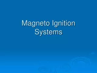
Welcome. Fluidized Bed Combustion Systems By M.RAJAVEL, SDGM / R&D/PCPS BHEL, TRICHY -14. What is Fluidization ?. Fluidized Bed. FLUIDISED BED BOILER. When Buoyancy Force balances Gravity Force. Buoyancy Force. Gravity Force. AIR. FUEL. ASH. Why call it Fluidized Bed ?.

E N D
Welcome Fluidized Bed Combustion Systems By M.RAJAVEL, SDGM / R&D/PCPS BHEL, TRICHY -14
What is Fluidization ? Fluidized Bed FLUIDISED BED BOILER When Buoyancy Force balances Gravity Force Buoyancy Force Gravity Force AIR FUEL ASH
Why call it Fluidized Bed ? Light object Floats ; Heavier ones Sink (Fixes Fuel Size) AIR AIR
Why call it Fluidized Bed ? • Horizontality Maintained • (Fixes Ash drain mechanism from Bed) ASH ASH ASH Fixed Bed Fluidised Bed
Why call it Fluidized Bed ? • Pressure drop is Bed Height • (Fixes Fan Power) Umf P B A B A Flow / Velocity AIR AIR
What is Fluidization ? Fixed Bed STOKER FIRED BOILER Buoyancy Force When Gravitational Force is predominant ASH FUEL Upto 25mm AIR
Why call it Fluidized Bed ? FLUIDISED BED BOILER A Bed of Solid Particles exhibit the properties of a FLUID namely: • Lighter objects float heavier ones sink • Pressure drop is Bed Height • Horizontality maintained hence termed as Fluidized Bed AIR FUEL ASH
How does a Fluidized Bed work ? The Bed of solid particles have to be retained at that size: Combustion Temperature has to be well below ash fusion temperature • Heat transfer walls are enclosed • Ash does not fuse - no slagging • Heat transfer by Gas / Particles Convection & Radiation • Fuel size upto 10mm - No PULVERISING • Ash soft amorphous state - less erosion FLUIDISED BED BOILER AIR FUEL ASH
How does a Fluidized Bed work ? When Fuel is injected into a Fluidized Bed of solid particles which is heated to Ignition Temperature of Fuel, it burns imparting heat to the entire bed Fuel Combustion takes place due to the heat available in the Bed Ash - millions of IGNITORS • Fuel of any Quality can be fired FLUIDISED BED BOILER FUEL AIR ASH
How does a Fluidized Bed work? Combustion of Solid Fuel leaves behind Ash. Finer fraction carried by flue gas, coarser fraction replenishes the bed solid inventory and excess is drained out by drain pipes Ash is dry and granular and is easily handled. FLUIDISED BED BOILER AIR FUEL ASH
Summary of Combustion Technologies PNEUMATIC TRANSPORT FIXED BED FLUIDIZED BED PRESSURE DROP GAS FLOW/VELOCITY
Technology Comparison STOKER (FIXED BED) PULVERISED FIRING (ENTRAINED BED) FLUIDISED – BED FIRING FBC GAS GAS GAS FUEL FUEL AIR AIR FUEL FUEL AIR ASH ASH AIR ASH 2.3 - 3 m/s 1.2 - 6 m/s 4.6 - 6.1 m/s Vel 6000 m 300 - 1000 m 50 m Par 1600 C 1600 C 850 C Temp
Advantages of Fluidized Bed Combustion Boilers • Low combustion temperature- <900 DegC lead to less Nox emission. • Sulphur present in coal can be recovered in-situ by adding limestone. SOx emission can be reduced >90% • S + O2 SO2 • CaO + SO2 +1/2 (O2) --> CaSO4 • Poor quality coal/lignite, coal washery rejects, containing ash >70%, can be used. • Biomass fuel can be fired either independently or in combination with fossil fuels.
Advantages of Fluidized Bed Combustion Boilers • FBC Boilers can be operated in all loads without sacrificing combustion efficiency. • Fuel of size less than 6 m.m. is used in FBC boilers and hence need not be pulverised as does in P.F. Boilers. • No moving grate or burners in FBC boilers. • Ash does not fuse at 900 DegC and hence soot blowers are not required. • High combustion efficiency of fuel due to higher residence time and entire surface area of fuel in contact with air.
Stoker Fired Boilers • Moving Component (Travelling Grate) in the high temperature Furnace zone • Combustion temperature 1400 - 1600°C; heat transfer in furnace by Flame Radiation • Fuel Ignited by the already burning Fixed Bed • Fuel Combustion time limited to grate travel length - hence fuels of poorer quality than design do not burn fully • Due to grate cooling requirements a minimum air quantity is required - hence excess air is high at part loads • Very low relative movement between Fuel and Air
Fluidised Bed Combustion Boilers Atmospheric pressure Fluidised Bed Combustion Boilers (AFBC) Pressurised Fluidised Bed Combustion Boilers (PFBC) I
Atmospheric Fluidised Bed Combustion Boilers Bubbling Fluidised Bed Combustion Boilers (BFBC) Circulating Fluidised Bed Combustion Boilers (CFBC) I
FBC Test Facilities 10 t/hr BFBC Prototype Boiler - 1977 BFBC Test Facility-1986 Combustion Test Rig-1979 (90 t/hr Hot water)
AFBC Technology Development • 1981 : First 12 t/h Commercial Boiler commissioned • 1984 : First 10 MW power plant for Washery Rejects • 1987 : First 10 MW power plant for Straw • 1992 : First 20 MW (100 t/h) power plant for Rejects and Char • 2000 : Largest boiler in operation of 180 t/h (45 MW) • 2002 : Export of 17 MW Boilers to PT IBR Indonesia • 2003 : Largest Boiler (300 t/hr) offered • 2006 : Design of 120 MW Boiler ready • 2008 : 3x18 MW Order from PT KPP, Indonesia • 2009 : 2 X 180 t/hr BFBC Boiler order from JSPL, Angul 66 Boilers Contracted Over 2.5 million operating hours
Drum S H I Eco Coal Bunker DESH Air Heater EVA S H II E S P Main Steam Ash Feeder Air Distributor I D Fan P A Fan F D Fan Schematic of AFBC Boiler
AFBC Components 1 Steam Drum 2 Bed Superheater 3 Bed Evaporator 4 Convection Superheater 5 Economiser 6 Windbox 7 Air Distributor Plate 8 Hot Air Duct 9 Cold Air Duct 10 Air Preheater 1 10 5 4 9 2 3 7 8 6
Flow Diagram of CFBC Boiler - Separate FBHE DRUM Spiess Valve SECONDARY AIR ID Fan
Major Milestone -CFBC Technology Development • 1995 : First CFBC boiler of capacity 175 TPH contracted • 1995 : Utility size 2x125 Mwe capacity plant order received from • Surat Lignite plant (SLPP) • 2003 : RVUNL, Rajasthan -2x125 Mwe plant using high sulphur content • lignite (6%) • 2005 : First 2x250 MW CFBC power plant order received from • NLC,Neyveli. • 2008 : Export order received from New Calidonia to supply 405 TPH steam generator 28 CFBC Boilers Contracted .
Proximate Moisture % 4.50 Volatile Matter % 39.58 Ash % 3.77 Fixed Carbon % 52.15 HHV kcal/kg 7792 Ultimate Carbon % 78.36 Hydrogen % 5.04 Sulphur % 2.57 Nitrogen % 0.98 Moisture % 4.50 Ash % 3.77 Oxygen % 4.78 Typical Fuel analysis ( Assam Coal)
Chemical composition of fuel ash (Assam Coal) and limestone:
Supercritical 600 MWe CFBC Boiler- Baima, China • Research on supercritical CFB was started in 2003. A demonstration of 600MWe supercritical CFB was initiating in 2006 supported by government. • The first demonstration in Baima was approved in 2008, that shall be commissioned in 2011 Steam T : 571℃/569℃ Steam P : 25.4MPa Steam Flow: 1900t/h, Boiler efficiency: 92% SO2 : <300mg/Nm3, Nox : <200mg/Nm3, Generation efficiency:42%
Design of 600MWe Supercritical CFB Boiler , • Design features: • Vertical tube design with partial rifle tube ; • Mass flow rate is 1400kg/m2s • 6 cyclones with 6 external heat exchangers (EHEs); • Bottom ash drained from both two side walls through roller type ash cooler;
Design Feature: • Benson vertical tube water membrane, mass flow 800kg/M2S. • Twin furnace (with total cross section 15x28m2 and 55 m height) divided by a partition water wall. • Six cyclones with inner diameter 9m. • six external heat exchanger (EHE). • In furnace superheater panels. • The LT SH and LT RH in second pass. • The HT RH , the MT SH located in EHEs. • There are two options for the cyclone selection –steam cooled and insulated. • Water jacketed rotary ash cooler is used bed ash 2011.
Arrangement of 600MWe supercritical CFB Boiler of Tsinghua’s Design
Take Care of Our Environment Thanks for Your Patient Listening