Download
1 / 56
560 likes | 798 Views
File. View. Status. Command. Initialize. Download. Miscellaneous. Help. File. View. Status. Command. Initialize. Download. Miscellaneous. Help. File. View. Status. Command. Initialize. Download. Miscellaneous. Help. File. View. Status. Command. Initialize. Download.

E N D
File View Status Command Initialize Download Miscellaneous Help
File View Status Command Initialize Download Miscellaneous Help
File View Status Command Initialize Download Miscellaneous Help
File View Status Command Initialize Download Miscellaneous Help Toolbar shortcut buttons has been removed “Click on Toolbar box to set it back”
File View Status Command Initialize Download Miscellaneous Help Status Bar has been removed “Click on Status box to set it back”
File View Status Command Initialize Download Miscellaneous Help
File View Status Command Initialize Download Miscellaneous Help Inputs in Alarm: Displays all circuits in the alarm state. They will be displayed by their User Name and Descriptions. However it should be noted that circuits that are shunted (disable) will appear in this window when they are physically in the alarm state and disappear when they are physically secure, but theydo not generate activity in the Alarm Display window. Inputs in Trouble Short: Displays all circuits in the Trouble Short state. They will be displayed by the User Name & Descriptions. However it should be noted that circuits the are shunted (disabled) Will appear in this window when they are physically in the Trouble Short state and disappear when they are physically secured and they will generate activity in the Alarm Display window. Inputs in Trouble Open: Displays all circuits in the Trouble Open state . They will be displayed by the User Name & Descriptions. However it should be noted that circuits the are shunted (disabled) Will appear in this window when they are physically in the Trouble Open state and disappear when they are physically secured and they will generate activity in the Alarm Display window. Input Shunted: Displays all circuits that are shunted (disabled) By Manual Command or Event Schedule. They will be displayed by the User Name & Descriptions.
File View Status Command Initialize Download Miscellaneous Help Inputs Shunted ( Time Zone): Displays all circuits shunted (disable) by an assigned Time Zone. All circuits will be displayed by their User Name and Descriptions. Inputs Shunted (Temporary): Displays all circuits that are shunted (disable) by the Temporary Shunted Command with a predetermined amount of time. All circuits will be displayed by their User Name, the remaining time until the shunt is removed and their Description. Inputs Shunted By Open Areas: Displays all circuits shunted (disable) by the function of the Open/Close Area feature. All circuits will be displayed by their User Name and Description. Inputs Ignored: Inputs that have faulty sensors connected or not in service.
File View Status Command Initialize Download Miscellaneous Help Readers Unlocked: Displays what Readers are unlocked by Command, Event Schedule or Time Zone. Readers Locked-out: Displays Readers that have been given a Reader Locked Out Command or Event Schedule. Reader With Door Open: Displays Reader Doors that are currently open. Keypad Reader in Only Card Mode: Displays Keypad Readers that are set to Card Only Mode by an Event Schedule or Manual Command.
File View Status Command Initialize Download Miscellaneous Help Outputs Shunted: Displays which Outputs have been shunted by Command. Outputs On: Displays what Outputs have been turned on. Displays Transferred: Shows all Displays that are Offline.
File View Status Command Initialize Download Miscellaneous Help Trunk Lines Not Reporting: Displays the serial Trunk lines that have failed. In LAN systems, the virtual trunk line will show as failed. Controller Not Reporting: Displays ANX’s, GP1’s or AN1’s that are not reporting. Multiplexer Not Reporting: Displays ACP’s, RMC’s or AN2,4 & 5’s panels that not reporting. Computers Failed: Displays servers that have failed in a dual host system.
File View Status Command Initialize Download Miscellaneous Help Host Mode: Displays: Displays the status of the Dual Host Serial Switch (Auto Mode or Manual Mode). Threat Level: Displays any threat level in effect. Printers in Failure: Displays audit printer in failure. (Optional) Download Status: Displays what Panels and the Files that are currently being download. The following is an Example of what you will see: 000 – Downloading Has Begun = This tells you that the download has begun to Panel address 000. 000 – Downloading Circuits = This tells you that the Circuit file is being downloaded to Panel address 000.
File View Status Command Initialize Download Miscellaneous Help Group Shunt: Displays the Group Shunts that have been turned on. Group Shunt (Temp): Displays the Group Shunts that have been given a Temporary Time and what the remaining is. Reader Group Command: Displays Readers Groups that have been given Manual reader commands. Area Opened: Displays Area Opened by Card Readers or Manual Commands under the Open/Close feature.
File View Status Command Initialize Download Miscellaneous Help Circuits in Alarm: Displays all Remote Receivers circuits currently in alarm by User Name and description. Circuits in Trouble: (Not currently used). Circuits Shunted: Displays what circuits are shunted by Time zone, Event Schedule, or Manual Command. Extended Door time Status: Displays which Jetways or Doors are activated, and the time the door has been open over the total allowed open time. The time will increment until it equals the total time and will be shown in the following format. 10/100 = active for 10 minutes out of 10 total minutes. To see the current time remaining you must click the Refresh button.
File View Status Command Initialize Download Miscellaneous Help Active Reader Tour: Displays all Readers Tours in progress. Failed Reader Tours: Displays all Reader Tours that have failed. Unaccessed Readers: Displays the Readers that has not been accessed in the reader tour that is currently in process. Active Watch Tours: Displays all Watch Tours in process.
File View Status Command Initialize Download Miscellaneous Help
Reader Command Go: Unlocks door for the reader circuits preprogrammed lock release time. Emulates a valid access. Lock: Locks readers and will only grant access to cardholders with the right access requirements. Reader status will be set to Normal. Unlock: Unlocks all readers and allowing any cardholders to access readers even without the right access level or access requirements. Reader status will remain Unlocked. Card Only: Sets Key pad readers in Card only mode and grants access to cardholders with the right access requirements. Card + Key: Must use prox card and then key pad to complete access. Lockout: Prevents a Reader to be used by any Cardholder and all attempts to access the reader will be treated as an alarm. Card + Key – Open/Close: Is used with a special function feature that places the reader in a Card + Key function. If an authorized cardholder presents card at reader using a keypad the cardholder can Arm or Disarm points. Card Only – Extended Door Time: Is used with a special function feature that places the reader in a Card Only function.
Input and Group Input Shunt Command Enabled Command: Sets the input circuit from disable to enable mode Disable Command: Deactivates the input so that no alarms will be generated from the input and the input cannot be commanded by the system. Temporary Shunted: Deactivates the Input circuit temporarily for a given time. No alarms will be generated from the input and the input cannot be commanded at that time Operates the same as the Input Shunt Command. The difference is that you are sending commands to the programmed group of inputs instead of an individual input.
Output and Output Group Command Off Command: Turn the Output off Latched On Command: Will turn the output On until the Off command is set. Latched Pulse Command: This command applies to the Reader and Output circuits only and it will pulse the output for one (1) sec. and then off repeatedly until the Off command is sent. Momentary Short Command: This command applies to the Reader and Output circuits only and it will turn the output on for 6 seconds and then off. Momentary Long Command: This command applies to the Reader and Output circuits only and it will turn the output on for 20 seconds and then off. Normal/Enable Command: Returns the output from Disable mode Shunt/Disable Command: Deactivates the output so it cannot be commanded by the system Operates the same as the Output Command. The difference is that you are sending commands to the programmed group of outputs instead of an individual input.
Group Reader Command Lock Command: Used to Locks readers after prior Unlock command was sent. Only valid Access Requirements will be granted access to the facility/building after Lock Command is sent. Unlock Command: Sets the readers to remain unlocked until a Lock command is sent. Anyone will be granted access. Lockout Command: Prevents a reader to be used by any cardholders and all attempts to access the reader will treated as an alarm.
Reset Anti-passback This command will reset an Individual Card In/Out flag to ZERO (0). This enables the selected card one “free pass” from one area to another if Anti-pass back is being utilized. This option works in conjunction with Anti- pass back readers. This command will reset all access cards In/Out flag to ZERO (0). This enables all users one “free pass” from one area to another if Anti- pass back is being utilized.
Transfer Alarm Display Command The Transfer Display Alarm command allows you to send alarms programmed to a specific workstation to another workstation on a temporary basis.
Threat level Cardholder’s Threat Level Reader’s Threat Level This system function is used in conjunction with the Reader and Master Personnel Threat Levels. Any readers with a threat level lower than the system threat level will be disabled and anyone with an access card that is programmed with a threat lower than the system threat will be Denied Access. The command is sent to all intelligent controllers.
Open / close area This function is used to Open, Close or Check the status of an area. An authorized cardholder can also open an area by presenting the badge card then press * sign then the keypad number. This will open an area or sets the alarm on. To close the area present the badge card on the keypad reader then press the # sign then enter the keypad number to close an area or disarm an alarm.
Arm / disarm group Arm/Disarm Group works in conjunction with the Arm/Disarm Module In the main Alliance/Odyssey Server. Set a reader for an authorized cardholder to enable or Arm an Alarm through input , output and reader circuits
Inquire Gp1 / an1 Access Level Time Zone This function allows you to poll a GP1,AN1, ANL or ANX controller as to whether or not a specific card is currently saved in its database. The Access Level and Time Zone list are assigned to the Card Number’s Group Code.
Annunciate card and reader Annunciate Card: Shows all transactions of the annunciated card to be tracked on the Alarm Display. This is all called employee watch which shows you all the activity of cardholder. Annunciate Reader: Shows all transactions of the annunciated reader to be tracked on the Alarm Display. This is also called door watch which shows all the activity of a specific door or area where reader is.
Single point status and reader door status This function when executed displays the status of a single Input point. This function when executed will display the status of a Reader door contact.
Reader tour Using a Tour Card a Guard/Person presents his tour card at defined card readers that must be accessed in programmable period of time. This feature allows the Operator to define whether the reader allows access or only records the fact that the tour card(s) accessed the readers.
watch tour The tour may be started by a card reader or by user command. The tour may be stopped at any time as well as being able to be restarted at any sequence. Status shows all the tours that are active as well as any failed tours. History allows the user to get hard copy reports of both successful and unsuccessful tour activity.
Simulate reader Shows simulation of all Reader transactions on the Alarm Display
Simulate input alarm Shows simulation of all Input transactions on the Alarm Display
Void card This command allows you to quickly void a card which also changes the Master Personnel record status simultaneously to also void cardholder to have unassigned status and will not be granted access
File View Status Command Initialize Download Miscellaneous Help
File View Status Command Initialize Download Miscellaneous Help
File View Status Command Initialize Download Miscellaneous Help
File View Status Command Initialize Download Miscellaneous Help
File View Status Command Initialize Download Miscellaneous Help Pops up the Logged message box every time an alarm is acknowledge from the alarm display the Server and workstation.
File View Status Command Initialize Download Miscellaneous Help Is a pin number that when entered on the keypad allows access at a given Reader but sends a Duress alarm to all programmed Servers and Workstation alarm displays. The Duress code is initialized to “0” in the Receptors Security Management System
System reset System reset clears Trunk Line, Controllers and Multiplexor Failures from status and a new polling sequence will be started. If any Trunk Line, controllers and multiplexor are still in failure they will be reported.
System reset System reset clears Trunk Line, Controllers and Multiplexor Failures from status and a new polling sequence will be started. If any Trunk Line, controllers and multiplexor are still in failure they will be reported.
Void / reinstate code Works with the Badge Code on the Master Personnel record. If Badge Code 1 is voided through this option, all cards programmed with this badge code will become disable. You can then Re-instate this badge code and all cards will return to their previous operating level. Badge Code numbers can be assigned in the Master Personnel for specific Groups such as contractors, union workers, production workers and etc.
Void/Reinstate Code: Works with the Badge Code on the Master Personnel record. If Badge Code 1 is voided through this option, all cards programmed with this badge code will become disable. You can then Re-instate this badge code and all cards will return to their previous operating level. Badge Code numbers can be assigned in the Master Personnel for specific Groups such as contractors, union workers, production workers and etc.
File View Status Command Initialize Download Miscellaneous Help This function is for Security Systems with GP1 panels only, the location of the card system code associated to your system. Please note that EXTREME CARE should be taken when entering this window. Entering the wrong System Code will cause none of the access cards to work.
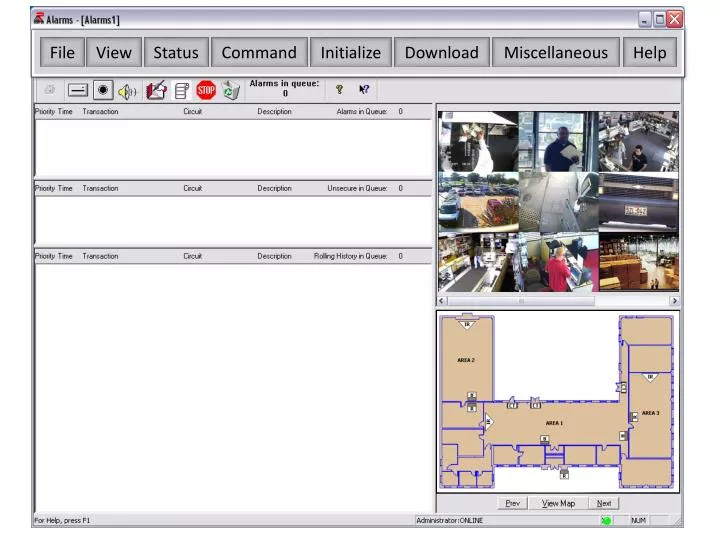
File View Status Command Initialize Download Miscellaneous Help When the same door alarm circuit or input alarm circuit comes in the “Alarm Queue” box the Alarm will overwrite itself and display only the last alarm for that circuit. In the “Rolling History in Queue” you will see all the alarms will be displayed for that circuit and they do not get overwritten in history. When you Initialize “Set Unacknowledged Mode” you will see all the alarms will be displayed for that circuit and they do not get overwritten when a new alarm comes in.
Set Unsecured mode Unsecured Mode will automatically remove alarms from the Unsecured in Queue window when alarms go secured
Use custom colors This option will works in conjunction with Set Palette under the Miscellaneous Tab in the alarm module.
File View Status Command Initialize Download Miscellaneous Help Allows the operator to manually download the database to the controller. Any changes to the Administration Module for Readers, Inputs/Outputs, Timezones, Timed Events, Access Levels, Group Codes, Elevators, Open/Close areas will be automatically downloaded to the Intelligent Controllers therefore manual downloads are optional. Changes to the Master Personnel will automatically be downloaded to the Intelligent Controller once the card holder presents his card at the readers. Once the Card is presented at the reader it will trigger the Server to automatically download all Master Personnel changes to the Intelligent Controller. Manual download can be done when changes are made to the Master Personnel so the Intelligent Controller will have the new information at the Intelligent Controller prior to New Cardholder presenting his card at reader.
Help File View Status Command Initialize Download Miscellaneous
1.) First double click on the Alarms in Queue transaction. 2.) Click on Predefined Messages to show all of the Log Messages in the Menu screen. 4.) Click Acknowledge to clear the Alarms in Queue transaction but the transaction in Rolling History in remains 3.) Click on New to create a new Log Messages or simply select from the list that defines the alarm or solution on how to resolve or acknowledge the Alarm. Log Message is used to determine alarm transaction in the Alarms in Queue window to Acknowledge alarms. RISG allows users to define or create a log messages for all Alarms in Queue transactions.