Download
1 / 39
520 likes | 1.04k Views
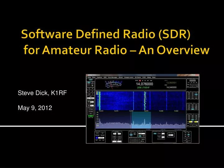
Steve Dick, K1RF May 9 , 2012. Software Defined Radio (SDR) for Amateur Radio – An Overview. What is Software Defined Radio?. As defined in Wikipedia:

E N D
Steve Dick, K1RF May 9, 2012 Software Defined Radio (SDR) for Amateur Radio – An Overview
What is Software Defined Radio? As defined in Wikipedia: • A software-defined radio system, or SDR, is a radiocommunication system where components that have been typically implemented in hardware (e.g. mixers, filters, amplifiers, modulators/demodulators, detectors, etc.) are instead implemented by means of software on a personal computer or embedded computing devices.
What is Software Defined Radio? • A basic SDR system may consist of a personal computer equipped with a sound card, or other analog-to-digital converter, preceded by some form of RF front end. Significant amounts of signal processing are handed over to the general-purpose processor, rather than being done in special-purpose hardware. Such a design produces a radio which can receive and transmit widely different radio protocols (sometimes referred to as waveforms) based solely on the software used. • In the long term, software-defined radios are expected to become the dominant technology in radio communications. Antenna I,Q R.F. Front End High Quality Sound Card P.C., Laptop, Netbook, or Embedded processor I,Q Example architecture
Some Distinctions • Modern conventional Radios are usually controllable via a computer with CAT or similar interfaces. These are Software Controlled radios, not software defined radios. • Modern conventional radios may use Digital Signal Processing for enhanced filtering for better performance than conventional filters and to eliminate multiple downconversions. These are NOT software defined radios. • Conventional radios having single sideband capability can feed audio to/from a PC for what is known as digital modes. This is real audio, not complex baseband I,Q. However, the digital mode modulation and demodulation can be considered software defined radio (modulation, demodulation, and detection functions)
Look and feel of Software Defined Radio • Does not look or feel like a real conventional radio. Uses a computer-based graphical user interface. No knobs!!! • Needs some getting used to after many years using a conventional radio. • Getting the software set up and working properly can be a challenge. It is definitely not plug and play and requires integrating multiple software packages • There are processing time lags on the P.C. (on the order of milliseconds). This is generally not a problem except when using Morse Code (CW). You can’t listen to your own signal and try to send Morse Code. Your brain gets confused from the time lag. A separate tone source with zero lag solves this problem • You can’t receive signals at the center of the spectrum. This is D.C. and soundcards don’t go down to D.C. Also, a lot of noise is picked up in this part of the spectrum (60 cycle hum, noise due to ground loops, etc) so you tune on either side of the spectrum center.
First, a few basic principles (P1 of 3):1. Sampling basics Sampling basics In 1933, Harry Nyquist discovered that to accurately recover all the components of a periodic waveform, it is necessary to sample a signal at twice the maximum bandwidth of the signal being measured. That minimum sampling frequency is called the Nyquist criterion. This may be expressed as: fs = 2 bw where fs is the sampling rate and bw is the bandwidth. See the math isn’t so bad, is it? In real life, a good rule of thumb is to use the 80% relationship: Bandwidth = 0.8 x ƒs/2 to allow for readily achievable filtering instead of “brick wall” filtering Courtesy Pentek - Software Defined Radio Handbook
First, a few basic principles (p 2 of 3):2. The mixer • The mixer is basically a multiplier (analog or digital) in which the local oscillator is multiplied by the incoming signal. For sine waves, the output signals are sum and difference frequencies of the local oscillator and the incoming signal frequencies. • One of the two signals is kept by filtering. The other signal is rejected by filtering. Any residual is known as an “image” and is undesireable Local oscillator = 14.000 MHz Incoming carrier = 14.001 MHz
First, a few basic principles (p 3 of 3):3. Selectivity: Q of a tuned circuit • Q = Quality factor • Q = F0/Delta F where • F = center frequency • Delta F = bandwidth • Higher Q = narrower bandwidth or high selectivity • Lower Q = wider bandwidth or low selectivity
Classic (Non-SDR) Radio – the Superheterodyne receiver • The conventional heterodyne radio receiver (A.K.A. Supersonic Heterodyne or Superheterodyne) shown has been in use for nearly a century. Let’s review the structure of the analog receiver so comparison to a digital receiver becomes apparent. • First the RF signal from the antenna is amplified, typically with a tuned RF stage that amplifies a region of the frequency band of interest. • This amplified RF signal is then fed into a mixer stage. The other input to the mixer comes from the local oscillator whose frequency is determined by the tuning control of the radio. The mixer translates the desired input signal to the IF (Intermediate Frequency) . • The IF stage is a bandpass amplifier that only lets one signal or radio station through. Common center frequencies for IF stages are 455 kHz and 10.7 MHz for commercial AM and FM broadcasts. • The demodulator recovers the original modulating signal from the IF output using one of several different schemes. For example, AM uses an envelope detector and FM uses a frequency discriminator. • In a typical home radio, the demodulated output is fed to an audio power amplifier which drives a speaker. I.F. frequency Trades off Image rejection vs. selectivity This diagram shows a single conversion (local oscillator plus mixer, IF Amp). Multiple conversions provide increased selectivity. So does DSP filtering used in modern designs. Courtesy Pentek Software Defined Radio Handbook Classic Addison 5 AM table radio Circa 1940
SDR Receiver Block Diagrams • A/D at front end at R.F. Then all digital conversion to baseband – but costly I,Q PC or Embedded processor Performs decimation Courtesy Pentek Software Defined Radio Handbook The “High Priced Spread” – Direct Digital Conversion • A/D at back end with A/D conversion done with sound card. – low cost Analog Downconverter AnalogRF Signal TayloeDetector Sound Card P.C. Or laptop RF Tuner I,Q I,Q Digital Local Oscillator (DDS or SI570) Dual flip-flop Divide by 4 Analog Baseband Samples Digital Baseband Samples The “Low Priced Spread” – soundcard-based
More on Digital Down Conversion • The “tuning knob” sets the digital local oscillator to the center of the baseband spectrum in the area of interest • The “Bandwidth” control sets the bandwidth of the low pass filter using different amounts of decimation. Wider bandwidths result in higher final output sample rates; narrower bandwidths result in lower final output sample rates. Low pass filter can typically be adjusted from megahertz to kilohertz Typical value 96 KHz baseband Sample rate (Sound card) Typical value 122.88 MHz Sample rate Courtesy Pentek Software Defined Radio Handbook
The RF Front-end generates baseband complex (I,Q) audio Antenna Baseband I,Q A/D Converter (sound card) and processing (PC) R.F. Front End • Band limited by • RF front end. • Typically limited to the KHz to 10s of KHz range Negative Frequencies Positive frequencies Zero frequency Bandwidth approaches +/- 48KHz with good soundcards
Seminal four-part article series on Software Defined Radio, QEX magazine 2002 • A Software Defined Radio for the Masses Part 1 • A Software Defined Radio for the Masses Part 2 • A Software Defined Radio for the Masses Part 3 • A Software Defined Radio for the Masses Part 4 Written by Gerald Youngblood, K5SDR, now CEO and President of FlexRadio Systems. In April of 2003 he founded FlexRadio Systems to market the first Software Defined Radio products to the Amateur Radio market
SDR Receiver Software Architecture Fists of Fourier Courtesy garage-shoppe.com Give me an I, give me a Q, and I can demodulate anything!!! Courtesy SDR for the masses, Part 1 The Fast Fourier Transform (FFT) does all the heavy lifting in SDR software to implement high performance filters in place of expensive hardware filters
High Performance Software Defined Radio at its Best! FlexRadio Systems introduces the FLEX-5000A™ ultra high performance Software Defined Radio transceivers. The FLEX-5000A integrates all I/Q data and hardware control over a single FireWire ® (IEEE-1394a) connection to a user provided computer. Examples of RF Front Ends • integrates all I/Q data and hardware control over a single FireWire ® (IEEE-1394a) connection to a user provided computer. • Top Performing Narrow-Spaced Two-Tone 3 rd Order IMD Dynamic Range of ~100 dB on 14 MHz Using a 2 KHz Spacing • Narrow Spaced 3 rd Order Intercept Point: Greater Than 39 dBm at 2 KHz Tone Spacing. • Integrated ultra high quality 192 KHz 24-bit ADC and DACs • Full Duplex Operation for Simultaneous Transmit and Receive • High Stability TCXO • 100 watts PEP on 160 to 6 meters • Cost $2799 Rear view Flex 5000A “The Cadillac of SDR” www.flexradio.com
Examples of SDR RF Front Ends c’d • Up to 5 band transceiver • 10 watts out minimum on all bands • QSD and QSE-based architecture • Semi-kit. All Surface mount components preassembled • IP3 30-32dBm • MDS is -116 to -122dBm. RF preamplifier on: MDS is from -130 to -133dBm. • Image rejection: -35 to -60 dB [hardware], better than 60dB [software] • RX sensitivity: 0.15-0.2uV for 10 dB S/N ratio. Max S/N measured: 70dB. • SFDR (Spurious free dynamic range) is 93-100dB these results are with signals spaced 5 kHz or more. • Built-in extras incl. CW keyer • Cost $299 less heatsink. You provide your own chassis,soundcard,PC Built by K1RF PCB ~ 8” X 8” Genesis Radio G11 www.genesisradio.com.au http://groups.yahoo.com/group/GenesisRadio/ Sample youtube video (SSB reception)
Examples of SDR RF Front Ends c’d UHFSDR Parts cost - ~$200.00 WB6DHW.com UHF SDR Yahoo Group
Examples of RF Front Ends c’d • Full duplex transceiver • Architecture based on Front end high speed ADC and FPGA based DDC and DUC • Built-in audio codec • Very high performance • ~ ½ watt output • Connects to PC via Ethernet • Approximate cost will be ~900.00
“We don’t need no Stinkin’ PCs” • Several companies or amateur radio groups have developed self-contained SDR transceivers that don’t use PCs. • They are based on very low cost DSP microcomputers that have significant digital signal processing capabilities, used in conjunction with low cost audio CODECs and a low cost programmable oscillator. • Example: Microchip dsPIC33FJ128MC804“Digital Signal Controller”. Cost ~$6 qty 1. 40MIPS, I2C, ADC and DAC, PIO • Low cost helper chips: • TI audio codec TLV320AIC3204IRHB • Silicon Labs Si570 10 Mhz TO 1.4 Ghz I2C Programmable XO/VCXO • There is also the first ever standalone digital modem,the NUE-PSK, a digital modem for PSK31 and RTTY field use ... without a PC!
“We don’t need no Stinkin’ PCs” NUE-PSK Digital Modem SDR Cube Transceiver SDR2GO www.nue-psk.com Featured in QEX Mar-Apr 2008 Base price $220 kit ~$70.00 Austin QRP club See Austin Summerfest 2010 www.sdr-cube.com Overview slides Complete kit $424
“We don’t need no Stinkin PCs”Elecraft KX3 –Where high volume commercial SDR is heading KX3 Self-contained operation Audio out to soundcard/PC For use with 3rd party software for SDR apps and digital modes • 160-6 meters, SSB/CQ/DATA/AM/FM modes • 10W PEP (100W with KXPA 100 amp) • Only 1.5 pounds (0.7Kg) • Current drain as low as 150 mA on receive • Ultra compact portable/mobile/home • Internal 8 - AA battery holder • Receiver performance rivals the best conventional transceivers • Base price $899 kit, $999 assembled
Basic low cost RF Front End Approach:The amazing Tayloe detector • Invented by Dan Tayloe, Patent no. 6,230,000, May 2001. • It has four unique properties: • Less than 1 db of conversion loss!!! • “Free” tracking bandpass selectivity (Q = 3,500 at 7 MHz), with a user definable bandwidth • Very high dynamic range - A high 3rd order intercept (+30 dbm). • An extremely compact and simple design using low cost components compared to other zero IF I-Q quadrature detectors • Conventional passive mixers generate sum and difference frequencies. Therefore, the conversion loss using an ideal mixer is at least 3 db, with a typical conversion loss of 4-6 db in practice • The Taylor detector produces onlya difference frequency!!! • Basic design useful into the GHz range • A.K.A. Quadrature sampling Detector (QSD)
The amazing Human Ear The human ear has about 130 dB of dynamic range. Sound cards strive to have undetectable distortion to the human ear for hi-fi applications
Why is this important? Because sound cards are designed to produce undetectable distortion to the human ear and have advanced significantly over the last few years in achieving that goal. • The standard for today’s audio reproduction and studio audio processing is 24 bits at 96 kbits/sec sampling rate, or even 192 kbits/sec sampling rate. • 24 bit soundcards come in many flavors and qualities, few if any approaching the theoretical maximum dynamic range of human hearing • Soundcard maximum theoretical dynamic range: 6.02 dB x 24 bits - 3 dB = 141.48 dB. Lets shave 20 dB off this number for worst case realism: 121 dB dynamic range. This dynamic range has undetectable distortion at normal listening levels. When applied to SDR applications, This is still an impressive dynamic range and approaches the dynamic range of the best military radios if the RF front end had perfect linearity and steps are taken to avoid noise contributing ground loops.
Representative sound cards used for SDR applications • Take your pick – everyone has their favorites • Can be mounted in PC or used via USB (Preferred for portability between different PCs or laptops) • Representative list with some user comments: • Emu 0202, works well but can be a bit touchy to set up correctly. • M- audio 2496 , works well easy set up.Essence stxpic- e, excellent and easy set up. • M-audio delta44, poor, pain in the *** to set set up • Sdr widget, works well. (kit) • Ederol FA66 • Sound Blaster X-FI surround 5.1 pro (good performance at low cost - ~ 49.00)
SoftrockLite II Schematic USB power Dual flip-flop Divide by 4 Tayloe Detector: CMOS analog switch, Capacitors, Dual low noise op-amp XTAL oscillator/buffer Bandpass filter This is the entire schematic for a very high performance single bandRF Front end – Incredible!!! Representative of Tayloe detector (Quadrature Sampling Detector) - based RF front ends
An inexpensive SDR sampler kit-The Softrock_40_R for $19.00 • http://www.kb9yig.com/To order • Join yahoo group:http://groups.yahoo.com/group/softrock40/ To check on availability (they go fast!!) See http://www.qrz.lt/ly1gp/SDR/ For a similar low cost SDR sampler TinySDR for 80M band
We don’t even need no stinkin’ hardware!! • Latest SDRs are moving to client-server architectures • Get on the internet and use someone else’s Antennas and RF baseband converter!! Antenna I,Q R.F. Front End High Quality Sound Card P.C. based server (Linux) I,Q P.C. based client (Linux or windows) Internet Yay! It works!
Log in to a remote server from your windows PC or laptop for free!! • Internet-based: No software required!!: www.websdr.org • More sophisticated but requires software download; Go to the following link for description: http://napan.ca/ghpsdr3/index.php/QtRadio_on_Windows • Download a zipped executable at:http://napan.com/ve9gj/qtradio-master.zip • Load to a new folder and extract contents • Run QTRdio.exe. Allow access if windows firewall blocks or only provides limited access • Click on Receiver /Configure and select audio card • Click on Receiver/Quick server list, highlight a server and connect (try different ones, some are more capable than other, some may not be operating) • You can now control the other person’s radio over the internet!! • There is also an Android Client for SDR servers!!
QT Radio screenshot You can select band, tune it with your mouse scroll wheel, select operating mode, look at received signal strength on S-meter, set control parameters, etc Pretty cool to let you try SDR with just a PC and internet connection
Digital Modes- So many modes, so little time • PSK31, PSK63, SSTV, HD SSTV, RTTY, MFSK16, MFSK32, MT63, Hellschreiber, Olivia, Packet, PACTOR , Throb, Contestia, JT6M, Ham DRM, Domino, DominoEX, DominoF, WSPR, ROS, SITOR, SITOR-A, SITOR-B, Swedish ARQ, Clover, CHIP, ALE, PAX, PAX-2, STANAG, HFDL, NAVTEX, SYNOP, COQUELET, AOR, WinDRM…. Between amateur and commercial services, there are tens of modes, perhapsapproaching 100!!! Courtesy George Heron, N2APB
Using Digital modes with SDR Software • SDR software can feed other third party software using other internal software interconnects for IQ audio transfer andreceiver/transmitter control. Virtual audio cable SDR software package Third Party software package (modulation, Demodulation, Control) Baseband I,Q Baseband I,Q Virtual Com Port (Control) Rocky, PowerSDR IQ, etc. Ham Radio Deluxe, FLDIGI, Digipan, etc.
Using digital modes with a conventional radio Software: - FLDIGI, … SSB transceiver A (fast) PC A (good) Sound Card (An external USB sound card is most flexible) Once you’ve wired your station for one HF mode, you can work another by just selecting a different mode in the software. Courtesy George Heron, N2APB
CW Skimmer, developed by Alex Shovkoplyas, VE3NEA • Seen above is a 25 KHz spectrum during a “Pileup”. This program simultaneously detects and decodes up to 128 Morse Code signals, finds and decodes the amateur radio call signs simultaneously across the displayed spectrum • Use of this program has been banned from use in many amateur radio contests due to providing too great an advantage. CW Skimmer can be downloaded here
PSK31 or or "Phase Shift Keying, 31 baud • Invented by Peter Martinez (G3PLX), Debuted in 1999 • Most popular HF digital mode • Heard near: 3.580, 7.070, 14.070, 21.070 MHz • The Undisputed King! • Used to conduct realtimeKeypoard to keyboard textchat • “Phase Shift Keying” is the the most popular of the newer digital modes. • Wealth of information on the web regarding BPSK (Binary PSK) and QPSK (Quadrature PSK) • Because bandwidth only 31Hz, many signals can fit into the same bandwidth occupied by an SSB signal (2.4kHz approx.). • Quite common to see 15 or more signals on a 2.5kHz waterfall display. Courtesy George Heron, N2APB
JT65 • Developed originally as part of the WSJT weak signal modes software package by Joe Taylor, K1JT, but is now open source • Can also be decoded by other packages, such as MultiPSK. • Has found a use on HF and can be found around 14.076MHz and 21.076MHz amongst others. • Signals that are virtually inaudible can give perfect copy so its performance is excellent on the noisy HF bands. • Transfer rate is slow, as are most modes that excel in low signal decoding. Courtesy George Heron, N2APB
And Now for Something Completely Different Software Defined Radio Software Demos: (Video, HDSDR)
Reference Links • DK3QN Example self-extracting WINRAD software and .wav files with instructions • HDSDR(former WinradHD) is an advanced version of Winrad • SDR Sharp a simple, small and fast PC-based DSP application for Software Defined Radio. It’s written in C# with both object design correctness and performance in mind • Signals, Samples and Stuff, a DSP tutorial parts 1, 2, 3, and4QEX Mar April 1998 • Comparison of “conventional”, “DDC based” and “soundcard based” receivers • Quadrature Signals, complex, not complicated on the DSPGURU.com site • Soundcard SDR Software • Virtual Audio Cable software by Eugene Muzychenko [ $35] • Software Defined Radio Explained – Fists of Fourier Parts 1, 2, 3, and 4 explains how the QSD detector works • VSP manager by Steve Nance - virtual com port software, free but requires amateur radio call sign) • FLDIGI digital mode software • Digipan for PSK31 and PSK63 • Ham Radio Deluxe, a widely used comprehensive program suite for CAT control, and digital modes • MultiPSK digital mode software • The VITA Radio Transport Protocol for SDR architectures future standard in work