Download
1 / 23
230 likes | 361 Views
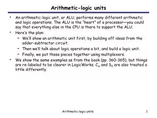
An arithmetic-logic unit, or ALU, performs many different arithmetic and logic operations. The ALU is the “heart” of a processor—you could say that everything else in the CPU is there to support the ALU. Here’s the plan:

E N D
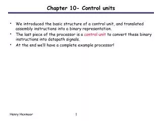
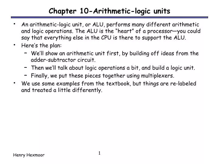
An arithmetic-logic unit, or ALU, performs many different arithmetic and logic operations. The ALU is the “heart” of a processor—you could say that everything else in the CPU is there to support the ALU. Here’s the plan: We’ll show an arithmetic unit first, by building off ideas from the adder-subtractor circuit. Then we’ll talk about logic operations a bit, and build a logic unit. Finally, we put these pieces together using multiplexers. We use some examples from the textbook, but things are re-labeled and treated a little differently. Chapter 10-Arithmetic-logic units
The basic four-bit adder always computes S = A + B + CI. But by changing what goes into the adder inputs A, B and CI, we can change the adder output S. This is also what we did to build the combined adder-subtractor circuit. The four-bit adder
Here the signal Sub and some XOR gates alter the adder inputs. When Sub = 0, the adder inputs A, B, CI are Y, X, 0, so the adder produces G = X + Y + 0, or just X + Y. When Sub = 1, the adder inputs are Y’, X and 1, so the adder output is G = X + Y’ + 1, or the two’s complement operation X - Y. It’s the adder-subtractor again!
So we have one adder performing two separate functions. “Sub” acts like a function select input which determines whether the circuit performs addition or subtraction. Circuit-wise, all “Sub” does is modify the adder’s inputs A and CI. The multi-talented adder
By following the same approach, we can use an adder to compute other functions as well. We just have to figure out which functions we want, and then put the right circuitry into the “Input Logic” box . Modifying the adder inputs
We already saw how to set adder inputs A, B and CI to compute either X + Y or X - Y. How can we produce the increment function G = X + 1? How about decrement: G = X - 1? How about transfer: G = X? (This can be useful.) This is almost the same as the increment function! One way: Set A = 0000, B = X, and CI = 1 A = 1111 (-1), B = X, CI = 0 A = 0000, B = X, CI = 0 Some more possible functions
The transfer and increment operations have the same A and B inputs, and differ only in the CI input. In general we can get additional functions (not all of them useful) by using both CI = 0 and CI = 1. Another example: Two’s-complement subtraction is obtained by setting A = Y’, B = X, and CI = 1, so G = X + Y’ + 1. If we keep A = Y’ and B = X, but set CI to 0, we get G = X + Y’. This turns out to be a ones’ complement subtraction operation. The role of CI
Here are some of the different possible arithmetic operations. We’ll need some way to specify which function we’re interested in, so we’ve randomly assigned a selection code to each operation. Table of arithmetic functions
This second table shows what the adder’s inputs should be for each of our eight desired arithmetic operations. Adder input CI is always the same as selection code bit S0. B is always set to X. A depends only on S2 and S1. These equations depend on both the desired operations and the assignment of selection codes. Mapping the table to an adder
All we need to do is compute the adder input A, given the arithmetic unit input Y and the function select code S (actually just S2 and S1). Here is an abbreviated truth table: We want to pick one of these four possible values for A, depending on S2 and S1. Building the input logic
We could build this circuit using primitive gates. If we want to use K-maps for simplification, then we should first expand out the abbreviated truth table. The Y that appears in the output column (A) is actually an input. We make that explicit in the table on the right. Remember A and Y are each 4 bits long! Primitive gate-based input logic
From the truth table, we can find an MSP: Again, we have to repeat this once for each bit Y3-Y0, connecting to the adder inputs A3-A0. This completes our arithmetic unit. Primitive gate implementation Ai = S2Yi’ + S1Yi
Most computers also support logical operations like AND, OR and NOT, but extended to multi-bit words instead of just single bits. To apply a logical operation to two words X and Y, apply the operation on each pair of bits Xi and Yi: We’ve already seen this informally in two’s-complement arithmetic, when we talked about “complementing” all the bits in a number. Bitwise operations 1011 AND 1110 1010 1011 OR 1110 1111 1011 XOR 1110 0101
Languages like C, C++ and Java provide bitwise logical operations: & (AND) | (OR) ^ (XOR) ~ (NOT) These operations treat each integer as a bunch of individual bits: 13 & 25 = 9 because 01101 & 11001 = 01001 They are not the same as the operators &&, || and !, which treat each integer as a single logical value (0 is false, everything else is true): 13 && 25 = 1 because true && true = true Bitwise operators are often used in programs to set a bunch of Boolean options, or flags, with one argument. Easy to represent sets of fixed universe size with bits: 1: is member, 0 not a member. Unions: OR, Intersections: AND Bitwise operations in programming
IP addresses are actually 32-bit binary numbers, and bitwise operations can be used to find network information. For example, you can bitwise-AND an address 192.168.10.43 with a “subnet mask” to find the “network address,” or which network the machine is connected to. 192.168. 10. 43 = 11000000.10101000.00001010.00101011 & 255.255.255.224 = 11111111.11111111.11111111.11100000 192.168. 10. 32 = 11000000.10101000.00001010.00100000 You can use bitwise-OR to generate a “broadcast address,” for sending data to all machines on the local network. 192.168. 10. 43 = 11000000.10101000.00001010.00101011 | 0. 0. 0. 31 = 00000000.00000000.00000000.00011111 192.168. 10. 63 = 11000000.10101000.00001010.00111111 Bitwise operations in networking
A logic unit supports different logical functions on two multi-bit inputs X and Y, producing an output G. This abbreviated table shows four possible functions and assigns a selection code S to each. We’ll just use multiplexers and some primitive gates to implement this. Again, we need one multiplexer for each bit of X and Y. Defining a logic unit
Inputs: X (4 bits) Y (4 bits) S (2 bits) Outputs: G (4 bits) Our simple logic unit
Now we have two pieces of the puzzle: An arithmetic unit that can compute eight functions on 4-bit inputs. A logic unit that can perform four functions on 4-bit inputs. We can combine these together into a single circuit, an arithmetic-logic unit (ALU). Combining the arithmetic and logic units
Our ALU function table • This table shows a sample function table for an ALU. • All of the arithmetic operations have S3=0, and all of the logical operations have S3=1. • These are the same functions we saw when we built our arithmetic and logic units a few minutes ago. • Since our ALU only has 4 logical operations, we don’t need S2. The operation done by the logic unit depends only on S1 and S0.
4 Cout should be ignored when logic operations are performed (when S3=1). 4 4 4 4 The arithmetic and logic units share the select inputs S1 and S0, but only the arithmetic unit uses S2. A complete ALU circuit The / and 4 on a line indicate that it’s actually four lines. • G is the final ALU output. • When S3 = 0, the final output comes from the arithmetic unit. • When S3 = 1, the output comes from the logic unit.
Both the arithmetic unit and the logic unit are “active” and produce outputs. The mux determines whether the final result comes from the arithmetic or logic unit. The output of the other one is effectively ignored. Our hardware scheme may seem like wasted effort, but it’s not really. “Deactivating” one or the other wouldn’t save that much time. We have to build hardware for both units anyway, so we might as well run them together. This is a very common use of multiplexers in logic design. Comments on the multiplexer
4 4 4 4 The completed ALU • This ALU is a good example of hierarchical design. • With the 12 inputs, the truth table would have had 212 = 4096 lines. That’s an awful lot of paper. • Instead, we were able to use components that we’ve seen before to construct the entire circuit from a couple of easy-to-understand components. • As always, we encapsulate the complete circuit in a “black box” so we can reuse it in fancier circuits.
We looked at: Building adders hierarchically, starting with one-bit full adders. Representations of negative numbers to simplify subtraction. Using adders to implement a variety of arithmetic functions. Logic functions applied to multi-bit quantities. Combining all of these operations into one unit, the ALU. Where are we now? We started at the very bottom, with primitive gates, and now we can understand a small but critical part of a CPU. This all built upon our knowledge of Boolean algebra, Karnaugh maps, multiplexers, circuit analysis and design, and data representations. ALU summary