Download
1 / 56
560 likes | 677 Views
Use Case Diagrams. CSIS3600 Fall 2002. *Why do we model?. Provide structure for problem solving Experiment to explore multiple solutions Furnish abstractions to manage complexity Reduce time-to-market for business problem solutions Decrease development costs Manage the risk of mistakes.

E N D
Use Case Diagrams CSIS3600 Fall 2002
*Why do we model? • Provide structure for problem solving • Experiment to explore multiple solutions • Furnish abstractions to manage complexity • Reduce time-to-market for business problem solutions • Decrease development costs • Manage the risk of mistakes
*The Challenge Tijuana “shantytown”: http://www.macalester.edu/~jschatz/residential.html
*The Vision Fallingwater: http://www.adelaide.net.au/~jpolias/FLW/Images/FallingWater.jpeg
*Why do we model graphically? • Graphics reveal data. • Edward TufteThe Visual Display of Quantitative Information, 1983 • 1 bitmap = 1 megaword. • Anonymous visual modeler
*Quick Tour • The UML is a graphical language for • specifying • visualizing • constructing • documenting the artifacts of software systems • Added to the list of OMG adopted technologies in November 1997 as UML 1.1 • Most recent minor revision is UML 1.3, adopted in November 1999 • Next minor revision will be UML 1.4, planned to be adopted in Q2 2001 • Next major revision will be UML 2.0, planned to be completed in 2002
UML Notation UML notation is useful for graphically depicting object oriented analysis and design models. • Models system requirements • Facilitates design decisions • Promotes communications among key players involved in the development effort • Integrates system views in a complete and consistent fashion • Employs a simple notation set
UML Notation • specifications for UML 1.4 visit: http://www.omg.org/technology/uml/ or http://www.omg.org/technology/documents/modeling_spec_catalog.htm(it’s 808 pages long!) Current version is v1.4
UML Diagrams • 12 basic diagrams divided into 3 categories • Structural Diagrams • Class Diagram, Object Diagram, Component Diagram, and Deployment Diagram. • Behavior Diagrams • Use Case Diagram, Sequence Diagram, Activity Diagram, Collaboration Diagram, and Statechart Diagram. • Model Management Diagrams • Packages, Subsystems, and Models
UML and OOAD The techniques drawn from the UML model for OOAD include: • Use cases - represent the functional requirements of the system. • Object diagrams- graphical depiction of the objects associated with the system. • Class diagrams - show the static structure of data and operations and their relationships in a logical view of the system. • Behavior diagrams or activity diagrams - model the behavior of the system. • State diagrams - represent how objects change their states in response to events. • Sequence diagrams - show interactions between objects. • Implementation diagrams including component diagrams and deployment diagrams. • Interaction or collaboration diagrams - Present an alternate or complement to the sequence diagram that models interactions between objects in the system.
OOAD and the SDLC • The object oriented development life cycle builds on the foundation of the SDLC. • But OOAD is iterative in design focusing on the evolution of the system throughout the system development process. • For instance models built in the analysis phase are reused and refined during the design phase.
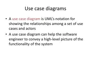
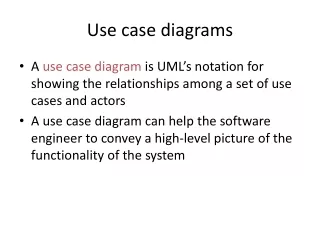
What is use case modeling? • use case model: a view of a system that emphasizes the behavior as it appears to outside users. A use case model partitions system functionality into transactions (‘use cases’) that are meaningful to users (‘actors’). • answers WHAT is the system to do
System Requirements and Use Cases • Use case diagrams are the primary focus of the requirements determination phase of analysis • Use cases describe system behavior from an external viewpoint and establish system boundaries • http://www.zoo.co.uk/~z0001039/PracGuides/pg_use_cases.htm
System Requirements and Use Cases • An important aspect of use cases is that they describe the system from the perspective of external users. • The process was designed to be inherently iterative so that developers wold involve users in discussions throughout the model development process. • This process also facilitates and enables the discovery of not yet identified system requirements. • Use cases analysis takes the place of the functional requirements stage used in SDLC.
Iterative Nature of Use Cases • Use cases control the formation of all other models used in the development process. • If user requirements change during the development process, the changes are first made in the use case model. • Changes to the use case dictate what changes need to be made in the other models.
Use Case Modeling • Jacobson (and others, 1992) pioneered the application of use case modeling for analyzing the functional requirements of a system. • Use case modeling depicts what the system is to do. • It is the process of identifying and modeling business events, who initiated them and how the system responds to them. • Use case modeling works to provide a solution to a problem by breaking down the entire scope of system functionality into many smaller views of system functionality. These smaller views of the system are often referred to as Packages. Within each package, the system is further broken down into task level functionality called 'Use Cases' • Complete Use Case modeling includes visualization (diagrams) and corresponding step-by-step documented descriptions of each identified use case.
Benefits of Use Cases • Use cases are used during the entire system development process. • During analysis the use cases are used to model functionality of the proposed system and are the starting point for identifying objects. • Use cases contain an enormous amount of system functionality detail. So they are a constant resource for validation and testing. • Use case is an invaluable vehicle for communication between developers and end users.
Definition of a Use Case A Use Case is a behaviorally related sequence of steps (a scenario), both automated and manual for the purpose of completing a single business task.
Use Case Modeling • A use case model is the visualization of a use case. • A use case model has two components: actors and use cases. • Actors initiate system activity - a use case - to complete some business task. • Note the simplicity of the model. The initial model itself it not detailed.
Use Case Diagram Fig. 3-53, UML Notation Guide
Characteristics of Actors • Actors represent anything that needs to interacts with the system to exchange information • An actor is a user or role that that is usually external to the system • An actor can be people as well as another system, hardware device, etc. • An actor does not represent a single individual • An actor always initiates a use case. • Actors are represented as stick people and Actors are given names. • Because actors are outside the system, they do not need to be described in detail.
Actors vs Users Actors are different from users. A user is anyone who uses the system. An actor is a role a user plays. An actor is a type or class of users - user is a specific instance of an actor (If the same user plays two roles, he would be represented as an instance in each class of actor, i.e. John Patton is both an instructor and advisor. He would be represented as an instance in both the actor called Instructor and the actor called Advisor.)
Characteristics of use cases • A use case is the function being described. • A use case always represents complete functionality not individual actions. • A use case is a complete sequence of related actions representing a specific way of using the system. • Use cases represent the behavior of the system in response to stimuli from an actor. • Use cases are represented as ellipses (oval). Use Case
Actors and Temporal Events Events triggered by time are called temporal events. • Who is the actor in a temporal event? • The actor is the system itself.
Temporal Event Example The backup of system data is automatically initiated to occur every night at 2:30 am. No one has to request the backup. It is a temporal event. The actor for this temporal event is the system itself.
Identifying Actors and Use Cases One place to start is to look at context model diagrams of the system. To identify use cases, Jacobson recommends asking: • What are the main tasks performed by each actor? • Will the actor read or update any information in the system? • Will the actor have to inform the system about changes outside the system? • Does the actor have to be informed about unexpected changes?
Constructing the Use Case Model • The goal is to build a use case diagram for each significantly different kind of scenario in the system. • Each scenario shows a different sequence of interactions between actors and the system with no or conditions. • Use cases are constructed after the actors and use cases have been identified. • Use cases are often grouped in to subsystems representing logical functional areas of the system. This partitioning aids in understanding the system architecture and is key to defining your development strategy - which use cases will be developed first and by whom.
Documenting the Use Case • Each use case is documented using a step-by-step description starting with the actor initiating the use case and ending with the business event. • The description includes objective of the use case, the actor that initiates the use case and the exchange of information between the actors and the use case.
Normal Course of Events First • The normal course of events is usually documented first. • Normal course of events includes major steps that happen the majority of the time • This allows you to concentrate on the system concept without getting bogged down in too many details.
Contents of a Use Case Document (normal course of events) • The name of the actor who initiated the case. • A high level description of the use case • A normal event course describing the use case's major steps from beginning to end of this interaction with the actor • Pre-condition describing the state the system is in before the use case is executed • Post-condition describing the state the system is in after the use case is executed • An assumptions section, which includes, any non-behavioral issues, such as performance or security, that are associated with the use case but aredifficult to model within the use case's course of events.
Alternate Course of Action A use case may also have alternate courses of actions • These alternates are deviations or branches from the normal course of events. • Alternates are documented in a separate use case.
Contents of a Use Case Document (alternate course of action) • The name of the actor who initiated the case • A high level description of the use case • A normal event course describing the use case's major steps from beginning to end of this interaction with the actor • Alternate course of action describing the major steps of deviation from the normal course of action • Pre-condition describing the state the system is in before the use case is executed • Post-condition describing the state the system is in after the use case is executed • An assumptions section, which includes, any non-behavioral issues, such as performance or security, that are associated with the use case but are difficult to model within the use case's course of events.
More on developing Use Cases • A use case may participate in relationships with other use cases. • There are two primary types of relationships - includes and extends. • There use to exist a relationship called ‘uses’ but it has gone away.
*Use Case Relationships Fig. 3-54, UML Notation Guide
Extends • An extends relationship, extends a use case by adding new behavior or actions. • The extends symbol is <<extends>>
When to use <<extends>> • Model alternate sequences through <<extends>> relationships • Remember a use case is usually modeled first using a normal course of actions. • Then "what if" conditions are considered and alternate courses of action are modeled in separate use cases. • These alternate use cases are related to the original use case by an "extends" relationship.
Includes • The includes relationship is used to prevent repetition of the steps required to other use cases • Includes - specifies that the base use case needs an additional use case in order to fully describe its processes. • It is mainly used to show common functionality that is shared by several use cases
When to use <<extends>> or <<includes>> • Use <<extends>> • Intent is to model an extension or variation of a complete use case • Use <<includes>> • The base use case must use another use case in order to complete its process
Diagram from Popkin Software: http://www.popkin.com/images/usecase.gif
Example of Use Case Diagram for a Course Registration System
Discover Actors • Actors are examined to determine their needs: • Registrar • Professor • Student • Billing System • Remember that use cases are within the system, actors are outside.
Discover Use Cases • A use case is a pattern of behavior the system exhibits • Use cases identified: • Maintain Registrar • Request Course Roster • Maintain Schedule • Register for courses
Put Use Cases with Actors • Each use case is a sequence of related transactions performed by an actor and a system in a dialogue. • Actors are examined to determine their needs: • Registrar - maintains curriculum • Professor - requests rosters • Student – registers for courses • Billing System - receives information related to billing from registration • Remember that use cases are within the system, actors are outside.
Relationships between use cases • A use case may participate in relationships with other use cases. • Two common relationships are uses and extends.
Look for Includes • Includes arise when one use case needs another use case.
Discover Extends • Extend extends a use case by adding new behavior or actions. An extends relationship shows optional behavior. The use case that is extended must make sense without the extension. Use cases in opposite order – Notice the direction of the arrow