Download
1 / 35
380 likes | 666 Views
Numerical Pilot Protection 7SD52 using digital wide-band communication. Numerical pilot protection relay 7SD52. Universally applicable. to. power system. n. configurations. up to. six ends. ,. containing. :. OH-. Lines. q. Cables. q. Transformers. q. For. digital.

E N D
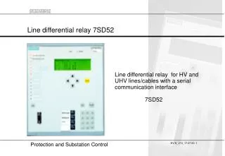
Numerical Pilot Protection 7SD52using digital wide-band communication
Numerical pilot protection relay 7SD52 Universally applicable to power system n configurations up to six ends , containing : OH- Lines q Cables q Transformers q For digital data transmissen n Via dedicated optical fibres q Via Communication networks q
Numerical Pilot Differential Protection Principle IA IB IAS , IAC DI DI IBS , IBC ID +j operate IA IAC stabilize IB ID Operate : ID = IA +IB Bias: IB = IA + IB Operating Criterium: ID K1 + K2.IS IBS + IAS IBC IB IA = IAS + j IAC IB = IBS + j IBC
Time reference iB iA B Location : A Location : B IM IB Relay A RE IB Relay B Definition of Synchronous Phasor: measured at different locations based on a common time reference
0 1 2 . . . n i k-n k Numerical pilot protection: Advanced Fourier analysis of the currents - Supress DC components, harmonics
Advanced Fourier Transformation - Optimized filtering coeffizients for 7SD52 -> Suppress DC 4 times better thanconventional Fourier-filters -> Archieve high sensitivity i0 i1 i2 iN Dt 0 1 2 3 . . . . N n 0 1 2 3 . . . N
Orthogonal Current Components (Advanced Fourier Filter) wt I(wt) Æ = 0 j IC I wt t = 0 IS
Numerical Pilot Differential Relay Propagation Time Measurement and Phasor Angle Correction A B I I ... IS(A), IC(A) tA1 tA1 tL1 tB1 tA2 tB2 tV tA3 tB3 tA4 tL2 .... tB4 IS(B), IC(B) tV tA1 tA5 tB3 IB(tA3) Propagation time: tL1= tL2= 1/2 x (tA-reception - tA1- tV) Corrected sampling instant: tB3= tA-reception -tL2 IB(tB3) = (tB3 - tL2) x (360O/Tperiod)
Example for the delay time calculation • Flight from Berlin <-> New York • You can not calculate the duration of a flight if you look at the clock in Berlin on departure and later note the local New York time on arrival. The reason are the different time zones.The relays are also in two time zones.. Each relay has it´s own 1 us resolution timer. • Tdepart / B->NY (6:00) --------------------> Tarrival / B->NY (8:00) • From the flight back from New York to Berlin the local departure time in NY and the arrival time in Berlin is: • T arrival / NY->B (23:00)<--------------- T depart / NY->B (9:00) • Under the assumption, that the flight to New York and the flight back from NY have the same durationthe relevant time results can be calculated. • The time difference between NY and B and the duration of the flight (transmission time) • Duration =(T arrival / B->NY-T depart / B->NY+ T arrival / NY->B- Tdepart / NY->B ) / 2 • Time difference = (Tdepart / B->NY - Tarrival / B->NY+ Tarrival / NY->B- Tdepart / NY->B ) / 2 • Duration = (8:00 - 6:00 + 23:00 - 9:00) / 2 = 8 hours (-> delay time) • Time diff. = (6 Uhr - 8 Uhr + 23 Uhr - 9 Uhr)/2 = 6 hours (-> difference between the time zones)
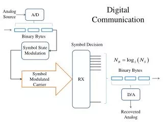
time data status + command Current vectors Coded message of current differential protection 7SD52 HDLC FRAME FORMAT Frame Check Seqence (FCS) Opening Flag Address Field (A) Control Field (C) Information Field (I) Closing Flag 01111110 16 bits relays address 8 or 16 bits any length 0 - N bits 32 bits 01111110 Synchronizing message validation
Monomode fibre 1300 ober 1550 nm I I a) Dedicated optic fibre I I Wire, G.703 Optic fibre or Microwave Further services: Telefon, Data transmission, etc. Further services: Telefon, Data transmission, etc. PCMMUX PCMMUX b) Channel of a data transmission system or of a data transmission network (Protection and PCM-device in the same room) Multimode optic fibres 850 nm Multimode optic fibres 850 nm I I O.F. O.F. G.703 G.703 Wire G.703 Optic fibre or microwave Further services: Telefon, Data transmission, etc. Further services: Telefon, Data transmission, etc. PCMMUX PCMMUX b) Channel of a data transmission system, or of a data transmission network (Protection and PCM-device not in the same room) Numerical pilot differential protection: Communication options
PCM multi- plexer PCM multi-plexer e o Application for a three terminal configuration Monomode fibre optic cable up to 35 km with 1300 nm interface Monomode fibre optic cable up to 10 km (1300 nm modul) Distance relay 7SA52 X21 G703.1 SDH comms-network e o 820 nm max. 3 km o e Option:I-REGB Comms- converter G703.1: 64 kBitX21: N*64 kBit (1N8) time synchronisation
Scope of functions / Hardware options Numerical line differential protection 7SD52 3Iph, and IE 4 U 8 binary inputs 16 contacts 1 - 2 protection interfaces System interface PC-interface Time synchronisation - For system configurations with up to 6 terminals - Fast high set charge comparision (subcycle trip)- Sensitive current phasor differential - Inrush restraint (2nd harmonic) and vector group adaption - CT saturation detector - Autoreclosure 1/3 pole - Overload protection - Switch on to fault protection - 4 remote commands, 24 remote signals ½*19´´ 16 binary inputs 24 contacts 24 binary inputs 32 contacts Option: 5 fast trip contacts 1*19´´
O O E O Communication Options • FO5: distance 1,5 km (with clock feed-back) • FO6 : distance 3km 820 nm1,5 km / 3 km internal • FO7 : distance 10km 1300 nm10 km internal • FO8: distance 35km O 1300 nm35 km internal • KU : hook-up to communication network X21 G703 external Km data for worst-case conditions
Protection interface 2Port E Synchronous N x 64kB/sec 7SD52 DIGSI 4; also for modem connectionand Browser service-interface Interfacemodul 1 RS485 or FO or RS232 DIGSI local Browser local-PC interface GPS-receiver Serial time sync. input Hardware option of the comms interfaces Remote line end 2 Plug in modules Remote line end 1 Protection interface 1Port D Synchronous N x 64kB/sec Subst. control interface Substation control communication modules Interfacemodul 2 FO (Fibre optic) or RS485or RS232 Available ProtocolsIEC - standard RS485 or FO
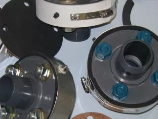
Main board of the relay with it´s Communication - Interfaces Main processor board of the relay Sockets for the communicationmodules
Adaptive Algorithm: Fast Charge comparison and very sensitive Phasor differential 87L 87L Charge comparison Fast normal trip stage IDiff>> Setting: 0,67*ILoadmax/IN Fast, <1cycle Phasor differential For high resistive faultsIDiff> Setting: 0,1-0,2 IN 1 cycle Phasor, fundamental frequency Every 5ms (128-512 bBit), 10 ms (64 kBit)
trip condition:IDiff >Ilow set and IDiff > IRestraint Adaptive differential relayingConsideration of CT- and communication-errors IDiffIN,load. trip I2 I3 I1 I2 restrain 0,15 I3 IDiff> I1 Through fault load I1 IrestrIN,Betr. 0.5 Calculated Phasor sum: IDiff = I1 + I2 + I3 IDiff = Ilow set Minimum pick-up: IRestrain = c.t. tolerance + Syncronising tolerance Restrain:
Protected Zone defined by c.t.1 and c.t.2 I2 I1 C.t. 1 C.t.2 I1 Source V2 IDiff IC Spill Current through Line Charging Capacitances Source V1 Kichhoff equation: I1 + I2 - IDiff - IC = 0 Service conditions: IDiff = 0, IC = I1 + I2 Difference equals charging current Pick-up value: IDiff> >2,5.. 4 • IC sensitive set point at short lines, minimum 0,1 IN
-I1 I1 I1´=0,95•I1 I2´=1,05•I1 IDiff=0,1 • I1 Setting above spill currents: c.t. error and line charging Resulting set point Set points: IDiff Percentage bias related to c.t. errors IDiff = |- I1´ + I2´|= f1• I1 + f2 • I2 Load: I1 = IN IDiff=0,1 • I1 = 0,1• IN Through Fault: I1 = 10 • IN IDiff = 10,5 • IN - 9,5 • IN = IN IDiff> Minimum pick-up related to line charging current I1 • IDiff> set point > line charging current • Percentage bias > Sum of c.t. errors
Approximated c.t. ToleranceBasis for the restraint current calculation IDiff I1 Fault current tolerance Tolerance of a real CT Load current tolerance ALFe / ALFN •IN,c.t I1 : parameter 7SD52 Example: 10P10, fB < 3%, fK at ALFN = 10%
Current transformer data C.t. Parameter c.t. e.g.5P20, 10VA Pi+ PN % tolerance at ALFN With PB = Pleads+ Prelay (0,1 VA) ALFe = ALFN Pi+ PB Thumb rule: Ri 0,1...0,2 * RN RN at 10 VA 10 => Ri 2 ALFe ALFN 2 VA+ 10 VA = = 4 2 VA+ 1 VA • Resulting Relay Parameter: • effective ALF / nominal ALF = 4 (calculation as per above) • IEC 44 -1: tolerance in load area up to ALFe / ALFN : 1% with 5P, 3% with 10P c.t.s • total error at accuracy limit nN = 5% with class, 5P and 10% 10 P
Internal restraint current calculation due to CT-errors The restraint current is the sum of the maximal expected CT-errors 5P20 20 VA 1600:1ALFe/ALFN = 5fLoad 1 = 1% (0,01) fSC 1 = 5% (0,05) 5P20 20 VA 1600:1ALFe/ALFN = 2fLoad 2 = 1% (0,01) fSC 2 = 5% (0,05) IN,load = 1600 A IC = 100 A 1200 A 5600 A 800 A 4800 A 10P10 10 VA 400:1ALFe/ALFN = 1fLoad 3 = 3% (0,03) fSC 3 = 10% (0,1) 400 A 800 A IStab = 2.5 • line charge currents (basic restraint value) + c.t. error currents IDiff = actual deviation of vector summation and charge summation Case 1 (Through load) IRest = 2,5 • 100 A + 800 A • 0,01 + 1200 A • 0,01 + 400 A • 0,03 = 282 A Irestr / IN,load = 0,176 Idiff = 100 A IDiff / IN,load = 0,063 Case 2 (Through fault) IRest = 2,5 • 100 A + 4800 A • 0,01 + 5600 A • 0,05 + 800 A • 0,1 = 658 A Irestrain / IN,load = 0,41 IDiff = 40 A IDiff / IN,load = 0,025
CT Saturation detector based on harmonic analysis t t |fn| |f1| ct I2 ct I1 Harmonic content of the differential current 2 0 Id = I1 - I2 0 Harmonic order 10 0
Charge comparison: Operating Principle I I 1 3 protected Line configuration I 4 1 2 3 4 Q =Q +Q +Q +Q diff I 2 1 2 3 4 Q Q Q Q 1 1 2 1 2 3 1 2 3 Q = Q Q =Q +Q Q =Q +Q +Q p art part part S 7SD52 7SD52 7SD52 2 2 3 4 3 3 4 4 4 Q =Q +Q +Q Q = Q +Q Q = Q Q part diff part part 1 2 3 4
|Q | diff Q > DIFF Charge Comparison:Charge calculation, Operating characteristic, Tripping times Operate diff Q D (internal fault) Charge calculation by numerical integration slope depending on Settable pick-up value Q =IDiff>> 1 Restraint Area qdiff12.dsf t t t t t t t 1 2 3 4 5 0 6 Calculated charge restraint valuefrom CT-errors , synch. errors QRest Current Measuring window Relay calculates the charge. Setting as current value IDiff>> 5 ms (50 Hz) Corrected time instantsafter end-to-end time synchronisation
7SD52 Pilot Protection:Sliding data windows fault- inception current, voltage voltage current time 5 ms charge and 20 ms phasor data windows
Familiar with digital communication networks Features of the relay to relay communication • Synchronous data transmission by HDLC- protocol • Permanent supervision of the data transmission • Measurement and compensation of signal transmission time(max. 20 ms) • Counts number of invalid telegramsBlocking the diff.protection if transmission failure rate is too high • Settings for the data transmission (N*64 kBit/s, N settable from 1 - 8, synchronous HDLC-protocol) • Communication device addresses(Protection devices are clearly assigned to a defined protection section) • Detection of reflected data in the loops in comms- network • Step 2: Microsecond exact time synchronisation via satellite (civil - IRIG-B)(If signal transmission time depends on the transmission direction, Online high resolution fault recorder)
side 2 I2 side 3 I3 I1 side 1 Ring and Chain topologie Automatic change fromclosed ring to chain, if one connection is lost or not available side 2 side 3 I2 Connection to other diff. relays I3 I3+I1 I2 I1+I2 I3 I1 I3+I1 I1+I2 side 1 Closed ring Partial current summation
Breaker-and-a-half Scheme, Through Fault Stabilisation busbar 2 busbar 2 87L To remote end 87L If = through fault current To remote end If = through fault current 87L busbar 1 busbar 1 Partial differential Full differential
Topologies: Chain topology for max. 6 line ends 1 2 3 PI1 PI1 PI2 PI1 PI2 PI - Protection Interface PI1 6 5 4 PI1 PI2 PI1 PI2
Topologies: Ring topology, 6 line ends 1 2 3 PI2 PI1 PI2 PI1 PI1 PI2 PI2 PI1 6 5 4 PI1 PI2 PI1 PI2 PI - Protection Interface