Download
1 / 18
180 likes | 276 Views
HQ02a2 test RESULTS. November 7 , 2013 FERMILAB. HQ02 test at Fermilab. First HQ quadrupole with coils (#15-17, #20) of the optimized design

E N D
HQ02a2 test RESULTS November 7, 2013 FERMILAB
HQ02 test at Fermilab • First HQ quadrupole with coils (#15-17, #20) of the optimized design • Only coil #15 previously tested in a mirror structure at Fermilab(HQM04). See“Test of Optimized 120-mm LARP Nb3Sn Quadrupole Coil Using Magnetic Mirror Structure”, IEEE Trans. on Applied Supercond., vol. 23, no. 3, p. 4002606, June 2013) HQ coil cross-section HQ02 parameters
HQ02 test at Fermilab (cont’d) 15kA header • HQ02(a) tested in May-Jun., 2013 • 15 kA header assembly with a lambda plate was used in this test • Test both at 1.9 K and 4.5 K • The magnet successfully reached the maximum allowed current of 15 kA at all temperatures • HQ02a2 test in Sep.-Oct., 2013 • 30 kA header assembly w/o lambda plate • Test at 2.2 K and 4.5 K • Test facility upgrades for the HQ02a2 test • External energy extraction system now provides 2.5 mΩand 5 mΩ dump resistors • Additional wiring added to the header assembly to accommodate more heaters (16) Lambda plate magnet
HQ02 voltage tap system • Voltage taps cover both the inner (IL) and outer (OL) coil layers • The magnet was equipped with the quench antenna and an acoustic sensor developed at LBNL (M. Marchevsky)
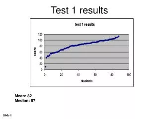
HQ02a2 quench training • Quench training performed at 2.2 K and witha regular ramp rate of 20 A/s • Excellent training memory demonstrated 89% of SSL 98% of SSL Ramp rate study PH tests T-dep. study QP study PH tests QP study
HQ02 quench locations • All training quenches in the pole-turn segments • Mostly coils #16 &20 participating in the training • Coil #15 previously trained up to 17 kA in a mirror structure HQM04
HQ02 ramp rate dependence study • Quenches at ramp rates of 150 A/s and above developed in the mid-plane area of coil 17.Low ramp rate quenches developed in the pole area of different coils • No ramp-down quenches at 13-300 A/s (HQ02a test)
HQ02 temperature dependence study • Mostly coil #16 quenching at intermediate temperatures 16.1 kA 16.2 kA 16.1 kA Current limit
HQ02 inductance measurements • HQ02a2 inductance measurement now is consistent with the HQ01 measurements at CERN • 15 kA header assembly tobe investigated for the possible issue with the whole coil signal used in the inductance measurements
More HQ02a2 tests results • No instability related issues. Hours of magnetic measurements performed at 80% of SSL (2.2 K) and at 90% of SSL (4.5 K) (J. DiMarco) • Quench propagation speed estimated • Ramp 13 (2.2 K): ~25 m/s at 86% of SSL, IL of coil 16 • Ramp 21 (2.2 K): ~30 m/s at 87% of SSL, ramp area of coil 16 • Ramp 55 (4.5 K): ~50 m/s at 98% of SSL, both the IL and OL of coil 17 • Voltage spike system, not functioning at the beginning, was fixed only for the second half of the test. Data analysis in progress • Due to possible issues with the whole coil signal in the previous test, AC loss measurements repeated in HQ02a2 (E. Ravaioli)
Quench Protection Study • Protection heater tests at currents up to 80% of SSL (T. Salmi) • Safe MIITs budget for the QP study • Postponed until HQ02b with increased pre-load • Based on previous HQ02a test 15-16 MIITs were set as a safe budget • QI study with small dump resistors • 2.5 mΩ and 5 mΩ dump resistors introduced in addition to 10 mΩ used HQ02a test • Test at currents up to 80% of SSL • Study of the quench propagation from the OL to the IL coil segments at currents up to 80% of SSL
QI study with different dump resistors • Tests performed with 5 mΩ and 10 mΩ dump resistors, as well as without the dump at 2.2 K. Only OL heaters used for the magnet protection • Very good reproducibility of the QI measurements in the current range of (60-70)% of SSL • Data analysis in progress
OL to IL quench propagation • OL protection heater induced quenches w/o dump • OL to IL quench propagation time t = t(IL quench) – t(OL quench) • OL to IL quench propagation time spread between coils shown for HQ02a2
Summary • HQ02 magnet with the Nb3Sn coils of the improved design and a stainless steel (SS) core in the conductor successfully tested at Fermilab • The magnet demonstrated stable performance and reached 98% of SSL at 4.5 K and 89% at 2.2 K • Test results demonstrated that a SS core can be introduced in the Nb3Sn coils without causing performance degradation • Currently the magnet warm-up is completed. The magnet will be extractedfrom the dewar and disconnected from the header assembly this week. Horizontal magnetic measurements are expected next week • HQ02 will be ready for shipping to LBNL around Nov. 15, 2013
RRR measurements in HQ02a Coil #15 Coil #16 Coil #20 Coil #17
HQ02 Short Sample Limit • Coil 17 with the lowest SSL at 4.6 K (~16.4 kA) A. Godeke
HQ02 inductance measurement • Measurements performed at 50-200 A/s