Download
1 / 27
270 likes | 447 Views
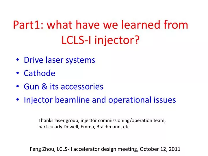
Part1: what have we learned from LCLS-I injector?. Drive laser systems Cathode Gun & its accessories Injector beamline and operational issues. Thanks laser group, injector commissioning/operation team, particularly Dowell, Emma, Brachmann, etc .

E N D
Part1: what have we learned from LCLS-I injector? • Drive laser systems • Cathode • Gun & its accessories • Injector beamline and operational issues Thanks laser group, injector commissioning/operation team, particularly Dowell, Emma, Brachmann, etc Feng Zhou, LCLS-II accelerator design meeting, October 12, 2011
Laser-related experience from LCLS-I • Uniform temporal profile is NOT necessary to get high quality beam, which simplifies laser system: single Gaussian with 2-4ps FWHM is good • Does spatial have to be very uniform? • Had some studies but need more experiments to make solid conclusion • Variable wavelength (PSI): it allows to reduce thermal emittance by moving wavelength to 260-270nm if QE is in very good shape • 100J is sufficient for 250pC if QE is ~4e-5 but we suggest to have more headroom (200J) in case we are in bad situation of poor QE
Emittance vs. laser pulse length(250pC) • SC is better with longer pulse length but time-dependent RF emittance ( ) is worse • Slice emittance is better with longer pulse length (RF kick has less impact on slice emittance)
Spatial Gaussian-cut (250pC) • Simulations and theory show that certain spatial Gaussian-cut beam has better emittance than the one with uniform. • LCLS MD result shows that with the Gaussian-cut • Slice emittance is 0.37m vs. 0.34m with uniform. The expected emittance improvement is probably washed out by non-smooth laser (Thales) and asymmetrical shoulders-cut. • Laser transmission through the iris is double of the uniform case • Plan more MD with Coherent laser Regular uniform LCLS measurements Gaussian-cut
Variable wavelength (PSI results) Hauri, et al., PRL 104, 234802 (2010)
Laser experience (con’t) • Coherent has narrower BW and quasi-Fourier limit temporal profile; it turns out 2ps for coherent vs. 400fs for Thales after compression. With Coherent: • Less stretching with the compressor to reach 3-4ps • UV tripler works better: smooth beam profile • After October downtime, we are planning to switch to Coherent • LCLS-II plans to use Coherent • What about our LCLS-II laser baseline: 2-pulse vs. 1-pulse? Need clear specifications: • What is charge/bunch in 2-pulse mode operation? • Should leave space to accommodate long delay line • Phase I R&D may study multi-bunch mode
Cathode – big concern although it is tiny • The cathode material physics is our weakest understanding; LCLS has used 3 cathodes: • 1st cathode (2007 - July 2008): QE was low but ok for commissioning • 2nd cathode (July 2008 - May 2011): QE was 4~5e-5 but quickly decayed to 2~3e-5 in ~7days at 120Hz and thus had to frequently move to next location took machine time and also NOT every location had good e-beam • 3rd cathode (May 2011 - present): original QE was only <1e-5, which can not be used for users’ operation; • Fortunately laser cleaning does work and works very well so far but still some concerns for future application to LCLS-II
Laser cleaning observations • During operations after cleaning, QE is not decayed but keeps gradually increased from 5.e-5 to 8.5e-5 from July 4 to October 4 2011: • Caused by continuous vacuum improvement (?) • Need a few days to condition the cleaned surface to achieve small emittance after cleaning; it is probably caused by following two factors: • Regular laser operations to smoothen out cleaned surface (?) • RF/vacuum conditioning (?) • E-beam performance can be improved greatly at the laser-cleaned spot even when it is in idle: • Immediately after cleaning: x/y=0.74/0.55m (150pC), and QE=5e-5. • After 6 wks RF/vacuum conditioning only: x/y=0.54/0.48m and mid slice 0.4m (250pC) and QE=6e-5.
QE and emittance evolutions after laser cleaning 3 months QE/gun vacuum 1 month emittance
Center area (x=0,y=0) For current routine operation off-center (X=0, y=-2.5mm) Idle spot
LCLS cathode alignment • Offset beam experiences RF kick, which impacts projected emittance but less on slice emittance (250pC) • Laser location on cathode w.r.t solenoid center within 2-mm looks OK (vs. 100s m @LCLS original requirement)
On LCLS thermal emittance • It was stated that the LCLS measured thermal emittance is 2x of theoretical expectation … • And then hope to get x2 thermal emittance improvement • Personally I am cautious for the above statement: • The Dowell’s model (0.6 m/mm) vs. measured (0.9 m/mm): already closes each other • According to the model: th~f(wf)~f(QEmeas) , the thermal emittance should increase if QE increases. But the LCLS reality may be NOT the case: • Measured LCLS data • Is the measured QE purely determined by work function? • The model probably does not include all realistic effects
QE=5e-5 QE=6.6e-5 QE=8.5e-5 QE=8.5e-5
What we learned from cathode • Current SLAC technique is not able to reliably provide cathode with nominal QE, 4~5e-5. • Laser cleaning works very well so far but need more understanding • It needs 1-2wks conditioning time to achieve good emittance • Do not fully understand why QE improves rather than decay: it is due to continuous vacuum improvement? • Is it reproducible for both QE and emittance evolutions • 1-2mm cathode offset looks OK to have a good beam • LCLS-II injector phase I R&D (cathode part): • To better understand laser cleaning : we may make solid conclusion after a few data points • New metal cathodes test given successful tests at ASTA • Tiny cathode may kill us if we do not pay attention!! • Good QE and long lifetime at 120Hz (more serious at potential 360Hz) are essentially needed.
LCLS gun & accessories Dowell, FLS 2010 LCLS-II gun duplicates LCLS-I except the replacement of dual-RF window to single RF window assembly (Jongewaard)
Injector beamline changes • A few beamline components are deleted and some added (PE’s list + Axel + Tor, etc); • These changes are already integrated into LCLS-II design.
Availability issues in injector operations • Laser lost RF lock • L0A & L0B: design 0.1% amplitude and 0.1 but does often cycle during operations • Laser (2%/0.4) and gun (0.1%/0.1) jittering or cycling • Need laser/RF experts to address these issues
LCLS injector modeling • It looks the model (ImpactT) has reasonably good predictions to the measurements • Has setup modeling using realistic laser beam (thanks Yuantao for the great help) • Ready for any kind of LCLS injector simulations
Part2: R&D Programs at LCLS-II Injector Phase I • The proposed programs are greatly benefited from: • PE’s list • Discussions with Brachmann, Emma, Huang, Jongewaard, Pellegrini, and Raubenheimer
LCLS-II injector phase I • Phase I beamline • Gun to BPM10 (just downstream of OTR2), which is same as phase II, temporary spectrometer (vert.) and a dump (new placement). • Installation of LH system might be delayed depending on time/budget • Available beam time at phase I (restricted by PPS): • Phase I of LCLS-II injector can be operated when FACET is operated since dump and some elements are in linac tunnel, and • Lockup from CID to sector-20 when FACET is downtime (LCLS-I still on) • Scheduled to be available in 2014-2015 (1-2 years period)?
Cu/CsBr films • ASTA needs to answer before applying into LCLS-II injector R&D: • Can CsBr survive in the transfer from test chamber to gun? • Can CsBr survive in the RF environment? • What about thermal emittance? Maldonado, Stanford university
Cu(111) & 70 injection • Cu(111) surface state emission channel gives a larger QE enhancement over normal emission in comparison with Cu(100) • To be careful: this is relative value!! • What about QE of Cu(100) vs. Cu(111) at normal incident injection? wf(100)=4.59eV vs. wf(111)=4.94eV, with same photon energy: • QE(111) < QE(100) although th(111) < th(100) – never free lunch! • QE(100) and QE(111) may be close if 70 injection. • But it is worth to test. W. Wan, et al LBL results
Velocity bunching NIM A 507 (2003) 310-313
Blow out regime • Taking advantage of the ultrafast (~100fs) of the laser as it expands longitudinally under the strong space-charge forces, and eventually evolves into ellipsoidal e-beam distributions. • The space charge forces are linear after expansion but a temporal asymmetry is observed • Comparison with ~ps laser
Trickle heating • Trickling heating may be minimized by changing optics of the LH – need studies Huang, et al., PRST-AB 13, 020703 (2010)