Download
1 / 19
190 likes | 313 Views
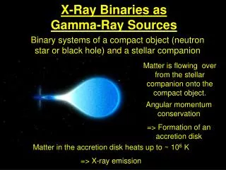
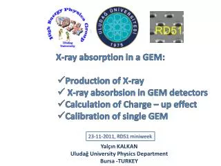
GEM technology for X-ray and Gamma imaging IMAGEM. Detector setup First results on X-ray imaging First results on Gamma ray imaging Requests. A triple GEM Chamber.

E N D
GEM technology for X-ray and Gamma imagingIMAGEM Detector setup First results on X-ray imaging First results on Gamma ray imaging Requests
A triple GEM Chamber A Gas Electron Multiplier (F.Sauli, NIM A386 531) is made by 50 m thick kapton foil, copper clad on each side and perforated by an high surface-density of bi-conical channels; Several triple GEM chambers have been built in Frascati in the LHCb Muon Chamber framework* 70 µm 140 µm GEM foil * M.Alfonsi et al., The Triple-GEM detector for the M1R1 muon station at LHCb, N14-182, 2005 IEEE NSS Conference, Puerto Rico
Particle conversion Cartesian Gain Small angle Readout Pads GEM Readout • Gain and readout functions on separate electrodes • Fast electron charge collected on patterned anode • Energy signal detected on lower GEM electrode 40% of electron signal 60% of electron signal
Radiography with GEM Radiography with Xray at 8 KeV of a small mammal (1200 x 640 Pixels) Pixel size of 50x50 m2 … Despite the good imaging properties of this readout structure, at higher rates (exceeding a few hundred kHz over the detector area) the reconstruction efficiency is limited by ambiguities due to multiple hits within one readout cycle, resulting from the intrinsic time resolution of the readout electronics (around hundred ns). With conventional two-dimensional projective read-out structure, no information is obtained which would allow the resolution of those multiple hits. 32 mm
Fast X-ray plasma diagnostics Readout: 32 2 mm2 pixels TIME-RESOLVED PLASMA ACTIVITY: (ENEA Frascati, Italy) Counts/50 µs D. Pacella et al, Rev. Scient. Instrum. 72 (2001) 1372 R. Bellazzini et al, Nucl. Instr. and Meth. A478(2002)13 Time (ms)
Gamma converter Different gamma converters have been studied trying to convert gamma rays up to hundreds KeV in electrons; the electrons produced are therefore drifted through the triple GEM structure to produce a detectable signals. A Large Electron Multipliers (LEM) made with 0.5 mm thick G10 layer drilled with 0.5 mm holes have been also tested. LEM triple GEM double GEM triple GEM
Pads and readout An array of 64 pad (8 cm long) has been realized on a 10x10 cm2 PCB. The pads are readout on the PCB back plane. The 64 pads are readout with LHCb ASDQ FEE. A VME DAQ, with scalers, reads the rates produced by gamma irradiation, in a defined time gate. ( 1 x 1 mm2 )
LEM BOX gamma Scan setup : Gamma ray • Several source has been used • Cesio (660 KeV) • Sodium (511 KeV) • Tecnezio (140 KeV) 3 mm lead screen Settings : Triple GEM @980 V LEM @500V
LEM BOX Scan setup : X ray Labview program developed by Chen for scan control, lem hv setting and DAQ Camac readout with a 12 channel scaler 3 mm lead screen XRay 6 KeV Xray 20 mA filament current Smooth movement for 20 sec total time For each “column” 100 ms acquisition time Electric plug image
Xray movie An X ray movie has been realized with this triple GEM gamma camera ; A rotating pencil box (with 2 pens inside) illuminated by a6 KeV X-Ray can be easily inspected Hz 0 2 4 6 8 cm Each frame has been kept in a time gate of100 ms Each pixel of 1x1 mm2 is measuring700 Hz The Xray gun behind the pencil box is running with a filament current of only30 mA
A SPECT image This image has been obtained with the same gamma camera set on a time gate of4 sec; The maximum rate measured on a single pad is15 Hzwith a background less than2 Hz. • Four 99Tc (140 KeV)sources 10x2 mm2wide have been put in front of the scanner system at a distance of3 cmfrom the camera : • First two sources : 4 mm apart • Second two : 6 mm apart 10 mm 4 mm 6 mm
Sci-fi gamma converter Trying to increase the chamber efficiency, some tests are in progress using the Kloe calorimeter structure as collimator and gamma converter lead collimator 2 cm scintillating fibers 3 cm photocathode 0 cm 1 cm 2 cm relative efficiency angle resolution of 50 mrad mrad
High density electronics The scanner system can be removed only if a high densityelectronics readout can be plugged on the pad backplane. ASIC ASIC ASIC We are studying and looking for “commercial” ASICs like : ALTRO (Alice), MEDIPIXII, BEETLE (LHCb), APV25 (Compass) to design and realize PCB able to accept a bonding of this chips. The main problem is the maximum detector capacitance acceptable. Are foreseen designs on fast readout through USB connection.
Requests for IMAGEM • Studies on converter: • New gamma converter using Kloe calorimeter structure • Photocathodes and GEMs • Studies on electronics : • Designs and realization of PCB • Bonding of chips on PCB • Designs and realization of fast readout through USB conn. Persone : F.Murtas 0.2 , P.Ciambrone X, C.Morone (TOV) 0.2, O.Schillaci (TOV) 0.5 Servizio Elettronica : 0.3 G.Corradi Consumo : 10 Keuro Missioni interno : 2 Keuro