Download
1 / 150
1.57k likes | 1.86k Views
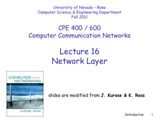
Lecture-A: The Network Layer & IP Addressing. Where is the network layer?. There are 7 layers from OSI model and 5 layers from TCP/IP model (as discussed previously!)

E N D
Where is the network layer? There are 7 layers from OSI model and 5 layers from TCP/IP model (as discussed previously!) From OSI, the Network layer restsbetween the upper layer called the Transport layer and the lower layer called the Data Link Layer. From the TCP/IP model, the Network layer is called the Internet layer and it rests between the upper Transportlayer and the lower Host to Network layer.
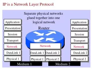
Network layer duties • The key is interconnecting different networks (various LAN technologies, telephone network, satellite link, ATM networks etc.) and making them look the same to the upper layer; i.e. logical gluing of heterogeneous physical networks together to look like a single network to the Transport & Application layer. • Additional notes: The transport layer should not be worried about the underlying physical network !
Network layer duties • The addresses must be uniquely and universally define the sole connection of a (host/router/machine/device/user) to the internet. Two devices on the internet can never have the same address. (Address per connection) Remember, network layer is independent of the data link layer. We cannot use the data link layer addresses !! Because these addresses depend on the technology used in the data link layer.
Network layer duties • Network layer encapsulates packets received from upper layer protocols and makes new packets. (Re-packaging). • This is a task common to all layers. • In the Internet model, packetizing is done by network layer protocol called IP – Internetworking Protocol. • The Protocol Data Units (PDU’s) coming from the transport layer must be placed in network-layer packets and sent to the data-link layer.
Network layer duties • A packet can travel through different networks. Each router decapsulates the IP datagram from the received frame, processes it and then encapsulates it in another frame. The format & size depend on the physical network. • Remember, the network layer must be able to operate on top of any data-link layer technology (Ethernet, Fast Ethernet, ATM etc.). All these technologies can handle a different packet length. • The network layer must be able to fragment transport layer PDUs into smaller units so that they can be transferred over various data-link layer technologies.
Network layer duties • Now that you have your network layer packet, where do you send it ? Each packet reaches its destination via several routes. • So, which route is suitable or optimum? Issue of speed, reliability, security etc. (routing algorithm) • Packet cannot choose the route; the routers connecting the LANs/WANs makes this decision. • (refer Chap-19 of Forouzan’s book).
Internetworking How can data be exchanged between networks? They need to be connected via routers/links to make an internetwork. • The above internetwork is made of 5 networks: 4 LANs and 1 WAN. • E.g. If host A needs to send a data packet to host D, the packet needs to go from A to S1, then from S1 to S3, and finally from S3 to D. Therefore the packet passes through 3 links.
Internetworks MAC layer protocol link-1 link-2 link-3 • Problem: how does S1 know that they should send out from f3 after packet arrive at f1 from A? (No provision in data-link layer to help S1 making the decision and the frame only contains the MAC addresses-pair of 1st link) • To solve the problem of delivery thru several links, the network layer was designed and responsible for host-to-host delivery and for routing the packets thru different routers.
Network layer at the Source Network layer at source is responsible to create a packet that carrier 2 universal addresses: Destination add. & Source add. The source network layer receives data from transport layer, adds the universal addresses of host A and host D. Make sure packet size correct & if too big, the packet is fragmented. Also, it can add fields for error control.
Network layer at the Router Network layer at the router is responsible for routing the packet. Another fragmentation is possible if necessary When a packet arrives, the router finds the interface from which the packet must be sent using routing table.
Network layer at the Destination Network layer at the Destination is responsible for address verification; it makes sure that Destination address on the packet is the same as the address of the receiving host. waits until all fragments arrive and reassembles them. It also checks for data corruption
Used in computer networks and (also in modern telephone networks). Packets of bits (not lines) are switched! Used in telephone networks for more than 100 years. A physical link is dedicated between Source and Destination. Data can be sent as a stream of bits without the need for packetising Switching/Routing Mechanism (Also called Connection-oriented networking) (Also called Connectionless networking)
Part A: Concept of IP Addressing in Network Layer
Internet Protocol (IP) • IP uses connectionless network-layer protocol. • IP is based on datagram switching/routing. • IP is unreliable !! • Don’t care how, as long as it arrives!!
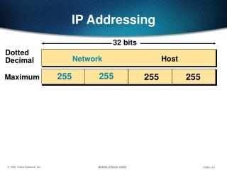
Relationship of Binary & Dotted-decimal notation
Example Change the following IP address from binary notation to dotted-decimal notation. 10000001 00001011 00001011 11101111 Solution 129.11.11.239
Example Change the following IP address from dotted-decimal notation to binary notation. 111.56.45.78 Solution 01101111 00111000 00101101 01001110
IP-Addressing • The general identifier used in network layer to identify each device connected to the Internet is called the Internet address or IP address. • Two types ID: Network Address & Host Address. • In IPv4, an IP address is a 32-bit binary address (4-bytes) that uniquely and universally defines the connection of a host or a router to the Internet. (Universal in the sense that the addressing system must be accepted by any host that wants to be connected to Internet). • Each IP address is unique and only defines 1 connection to the Internet. Two devices on the internet can never have the same address at the same time. (referring to IP Public addresses).
IP-Addressing • Two types of IP addressing: Classful vs. Classless • When a packet needs to be sent from s host to destination, it needs to pass from one node to the next. The network layer provides only host-to-host addressing; the data-link layer needs physical MAC addresses for node-to-node delivery. • Method to map these two addresses: ARP– Address Resolution Protocol.
IP Addresses Unicast Multi-cast
Classful Addressing: Finding the class in binary notation
Classful Addressing: Finding the class in decimal notation
Classful Addresses Classful addressing in IP is both inflexible and inefficient ! 0.0.0.0 to 127.255.255.255 128.0.0.0 to 191.255.255.255 192.0.0.0 to 223.255.255.255 allows 127 networks and 16 777 214 hosts on each network 24 bits = 224 -2: exclude 1st and last IP 7 bits = 27 -1: exclude 0.0.0.0 allows 16384 networks and 65534 hosts on each network 16 bits = 216 -2: exclude 1st and last IP 14 bits = 214 allows 2 097 152 networks and 254 hosts on each network 8 bits = 28 -2: exclude 1st and last IP 21 bits = 221 Note: In each network, the 1st IP address is the Network Address (e.g. 73.0.0.0) and the last IP address is for special purpose (e.g. 73.255.255.255).
Classful Addressing • Unicast address: one source to one destination; Class A, B & C. • Multicast address: one source to a group of destination: only as destination address not source address; Class-D. • IP addresses in class A, B, C are divided into different length of: • Network-ID (netid) and Host-ID (hostid) • Classes and Blocks concept: - for example: • In class-A, 1st block covers from 0.0.0.0 to 0.255.255.255 (net-ID 0) • 2nd block covers from 1.0.0.0 to 1.255.255.255 (net-ID 1) • last block covers from 127.0.0.0 to 127.255.255.255 (net-ID 127) • Note that: block = number of available networks in each class • One problem with classful addressing is that each class is divided into a fixed number of blocks with fixed size. (read Forouzan’s text) • Plenty of IP addresses wasted!!! in classful addressing method.
128 Blocks in class A 1st IP used to identify organisation to the rest of Internet 3 bytes = 224 Last IP reserved for special purpose; not allowed to use Millions of class A addresses are wasted.
16384 Blocks in class B 16 blocks for private addressees leaving 16368 blocks Class B for midsize organisation. 16384 organizations are class-B Many of class B addresses are wasted.
2,097,152 Blocks in class C 256 blocks for private addressees leaving 2,096,896 blocks Class C for small organisation. Limited IP address in each blocks, which is smaller than the needs of most organisations
Class D addresses are used for multicasting; there is only one block in this class. Class E addresses are reservedfor special purposes; most of the block is wasted.
The network address is the first address. The network address defines the network to the rest of the Internet. Given the network address, we can find the class of the address, the block, and the range of the addresses in the block Network Addresses
Figure 4-13 Network addresses In classful addressing, the network address (the first address in the block) is the one that is assigned to the organization.
Example Given the network address 17.0.0.0, find the class, the block, and the range of the addresses. Solution The class is A because the first byte is between 0 and 127. The block has a netid of 17. The addresses range from 17.0.0.0 to 17.255.255.255.
Example Given the network address 132.21.0.0, find the class, the block, and the range of the addresses. Solution The class is B because the first byte is between 128 and 191. The block has a netid of 132.21. The addresses range: 132.21.0.0 to 132.21.255.255.
Example Given the network address 220.34.76.0, find the class, the block, and the range of the addresses. Solution The class is C because the first byte is between 192 and 223. The block has a netid of 220.34.76. The addresses range from 220.34.76.0 to 220.34.76.255.
Sample Internet Note: When it comes to routing, the outside world recognises the network via network address, not the individual host-IPs
Network Addresses The network address is the beginning address of each block. It can be found by applying the default mask to any of the IP addresses in the block. It retains the netid of the block and sets the hostid to zero. We must not apply the default mask of one class to an address belonging to another class.
Part B: Concepts of Subnet & Mask in Network Layer
Mask A mask is a 32-bit binary number or 4-bytes that gives the first address in the block (the network address) when bitwise ANDed with an address in the block.
Default Mask Default class A mask is 255.0.0.0 Default class B mask is 255.255.0.0 Default class C mask is 255.255.255.0
Example Given the address 23.56.7.91 and the default class A mask, find the beginning address (network address). Solution The default mask is 255.0.0.0, which means that only the first byte is preserved and the other 3 bytes are set to 0s. The network address is 23.0.0.0.
Example Given the address 132.6.17.85 and the default class B mask, find network address. Solution The default mask is 255.255.0.0, which means that the first 2 bytes are preserved and the other 2 bytes are set to 0s. The network address is 132.6.0.0.
Example Given the address 201.180.56.5 and the class C default mask, find the network address. Solution The default mask is 255.255.255.0, which means that the first 3 bytes are preserved and the last byte is set to 0. The network address is 201.180.56.0.