Download
1 / 16
160 likes | 265 Views
Some of the Unusual Cryogenic Problems Addressed in the ERL Cryomodules. Eric Smith 17 January 2014. Ideal Practical 150 COP 700 total 5.2MW roomT 70 COP 230 total 2.1MW roomT 5.5 COP 15 total 2.2 MW roomT. Operational Heat Loads.

E N D
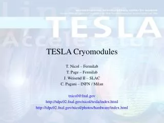
Some of the Unusual Cryogenic Problems Addressed in the ERL Cryomodules Eric Smith 17 January 2014
Ideal Practical 150 COP 700 total 5.2MW roomT 70 COP 230 total 2.1MW roomT 5.5 COP 15 total 2.2 MW roomT Operational Heat Loads These are design heat loads. Allow for a factor of 1.5 as a safety margin.
40-80K cooling @ 20bar-18bar . Chosen to allow large temperature rise in gas (so fewer g/s circulating—compressor power is major cost), high pressure gives higher density, lower pressure drops in heat exchangers, pressure is a “natural” choice for refrigeration system. Good for minimizing radiative heat load. Tested in other big systems.4.5-6K cooling @ 3bar. Needs to be well below Tc for the Nb cavities to keep Q high at ends. Needs to be above the critical pressure for helium to ensure that we always have single-phase flow (important for even flow distribution in our parallel cooling flows scheme). Operation very near critical point of helium almost doubles heat capacity of the helium gas (need to circulate less gas to maintain small temperature rises).1.8K (with distribution from refrigerator as 2K @ 1.2 bar). Subcooled distribution is single-phase. Good compromise on Q factor. Very good heat transfer. Adequately high vapor pressure (16mbar).
Can we just use copper straps to cool the HOM loads?Maximal load of 400 Watts into an HOM load (average 200W).Suppose we are willing to accept a temperature difference of 40K between our load and a heat sink at a distance of 30 cm.Thermal conductivity of copper around 80K is 4W/cm K.We would need a cross-section for the copper braid of:400W / (4W/cm K) * 30 cm / 20K = 75 cm2While this could be provided by a solid bar 4” in diameter, it doesn’t really quite provide the flexibility or convenience which we normally associate with a braid! We need to use convective cooling rather than conductive cooling. (Same reason we run cooling water lines near apparatus at room temperature).
Delivering about 1 g/s through each of the 40-80K cooling channels in the HOM loads gives an appropriate temperature rise of 40K in each of these components under nominal operating conditions. How do we ensure that the ones experiencing more or less than the normal heat load still get a fair share of the helium flow? How do we at the same time distribute an equitable amount of cooling to the 40-80K intercepts on the input couplers, which have only 5% as big a heat load?If we operate at, say for example, 25% beam current (6% of HOM heat load), can we adjust flow rate down so as to operate refrigerator more efficiently?How can we smoothly transition from operation at low beam current to normal operation quickly without disrupting refrigerator operation?
DP=const*L*h0.25*mdot1.75/D4.75/r while h a T0.6 r a 1/T So, for fixed geometry, DP a mdot1.75*T1.15Put a moderate length of a smaller diameter tube before the heat loads so that much of pressure drop is load independent.
It won’t work to mount electrical heaters on the outside of the grade 5 Titanium ring to mimic an actual rf heat load on the SiC. We instead need to have a separate series heater assembly on the helium feed circuit.
Thermal Contraction Effects on ConstructionThe large HGRP (of titanium) is fixed at roughly the center of the 10m-long room-temperature cryomodule vacuum vessel.Beamline components are suspended from the HGRP (and fixed near the center longitudinally).Between cryomodules, the titanium HGRP needs a bellows to allow 20mm of thermal shrinkage, 40K coolant supply (aluminum) needs 40mm, 5K pipes (stainless steel) need 30mm. This means that bellows are needed for all of these transitions. Need both constraint to prevent squirming and to reduce whistling.
Cooldown from Room TemperatureThe cooldown needs to be done at a rather slow pace, because there is a very large mass with large heat capacity (some tons of metal per cryomodule). Some parts being cold while others are hot could result in severe distortions, even breakage, because of local thermal contraction. The intended solution is to mix the cold gas coming out of the refrigerator with warm gas at an appropriate rate to keep the gas stream always about 20K colder than the warmest part of the cryostat while keeping the total gas flow as high as possible to minimize the total cooldown time. One specific example of the difficulties is that the incoming stream intended to cool many intercepts to 40K eventually comes in intimate contact with over a ton of aluminum radiation shield before ever touching inner parts of the cryostat, entering at one end. So one end of the shield will always tend to be about 20K colder than the other end through most of the cooldown.
Special Complications of the 1.8K SystemSuperfluid helium is a spectacularly good thermal conductor, except when it isn’t! It stops being very good at a heat flux of around 1W/cm2, which puts a minimum diameter on the size of the chimneys connecting the helium jackets on the rf cavities to the 2K-2phase line, and puts restraints on the minimum depth of liquid in that line, and on how close the helium jacket can come to the niobium cavities. These are not very restrictive if the cavities in fact achieve a Q = 2 x 10¹⁰, but should be large enough so that if a few of the 400 cavities should be a factor of 3 or 4 worse, they could still be operated.Wind velocity across the gas/liquid surface in the 2K-2phase line. Excessive flow velocity of the vapor will excite surface waves on the surface. With 1.7g/s flowing out of half the cavities in the module toward the center, have about 0.75m/s surface speed if liquid helium is filled to about 1/3 of tube height. This is OK (by simulation).
Interestingly, there is nearly 0.5mbar pressure difference along the length of the half-linac string (out of 16mbar) in the 270mm HGRP. If we put an access tube at each end of the 2K-2phase line into this pipe (as we did, for instance, in the injector cryomodule), this pressure gradient would shunt a significant gas flow through the 2K-2phase line in parallel with the main flow in the HGRP on the end of the string nearest to the refrigeration plant. This would probably still leave a stratified gas layer, but would give very little margin for safety. Thus we will be using a single port in the middle of the tube in each cryomodule.There are several reasons why it wouldn’t work to have no separate 2K-2phase line in each cryomodule, but just to connect the helium vessels for each cavity directly into the HGRP. These include high flow velocities (up to 6m/s at return end of HGRP) which would cause significant risk of wave generation, much larger helium inventory, and a helium depth several centimeters greater at one end of the linac than the other (liquid helium is very low density).