Download
1 / 155
1.7k likes | 2.62k Views
INJECTION MOULDING. Historical Background. A single-action hydraulic injection machine was designed in the U.S.A. in 1870 by Hyatt Heating-cylinder design was first recognised in a patent issued to Adam Gastron in 1932.

E N D
INJECTION MOULDING CORPORATE TRAINING AND PLANNING
Historical Background • A single-action hydraulic injection machine was designed in the U.S.A. in 1870 by Hyatt • Heating-cylinder design was first recognised in a patent issued to Adam Gastron in 1932. • Large-scale development of injection moulding machinery design towards the machines we know today did not occur until the 1950's in Germany CORPORATE TRAINING AND PLANNING
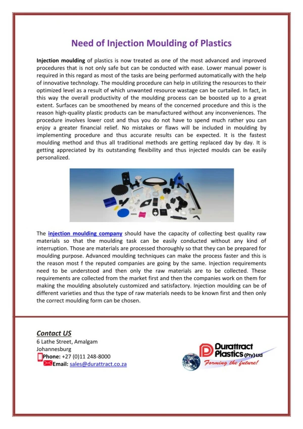
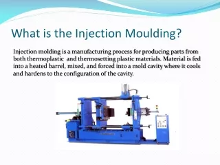
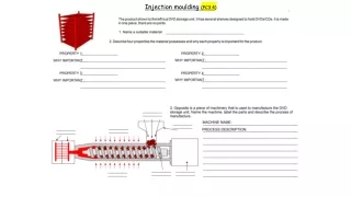
Injection Moulding Process – Over View Solid Wide neck, Flat Product is made like bucket, cabinets, Automobile & Industrial parts etc…. by injecting molten thermoplastic material in to a closed mould which is relatively cool. CORPORATE TRAINING AND PLANNING
Type of Injection Moulding Machine • Hand Injection Moulding M/C • Plunger type Injection Moulding M/C • Reciprocating Screw Type Injection Moulding M/C CORPORATE TRAINING AND PLANNING
Hand Injection Moulding Machine vertical machine consists of Barrel, Plunger, Band Heaters along with energy regulator, Rack & Pinion system for Injecting the material by the plunger, a torpedo and nozzle. CORPORATE TRAINING AND PLANNING
Plunger Type Injection Moulding Machine Vertical & Horizontal Plunger Type Injection Moulding Machine CORPORATE TRAINING AND PLANNING
The Reciprocating Screw • The feeding zone • The compressing (or transition) zone • The metering zone CORPORATE TRAINING AND PLANNING
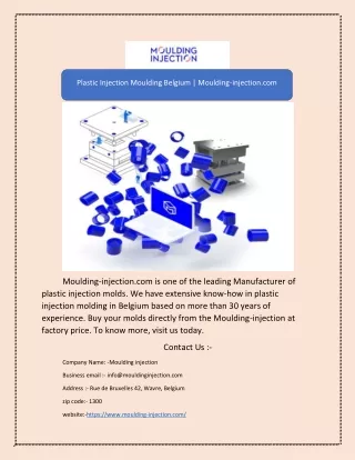
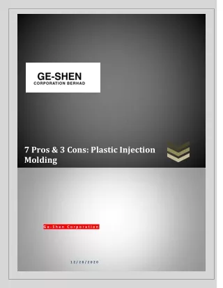
Machine components CORPORATE TRAINING AND PLANNING
The Injection Process • Plasticises the material by reciprocating Screw. • Injects the molten material to a closed mould • via a channel system of gates and runners. • Cools the Mould. • Refills the material for the next cycle. • Ejects the Product. • Closes the Mould for further cycle. CORPORATE TRAINING AND PLANNING
Injection Moulded Items CORPORATE TRAINING AND PLANNING
Injection Moulded Items CORPORATE TRAINING AND PLANNING
Injection Moulded Items CORPORATE TRAINING AND PLANNING
Advantages of Injection Moulding Process • Parts can be produced at high production rates. • Large volume production is possible. • Relatively low labour cost per unit is obtainable. • Process is highly susceptible to automation. • Parts require little or no finishing. • Many different surfaces, colours, and finishes are available. • Good decoration is possible. • For many shapes this process is the most economical way to fabricate. • Process permits the manufacture of very small parts which are almost impossible to fabricate in quantities by other methods. CORPORATE TRAINING AND PLANNING
Advantages of Injection Moulding Process • Minimal scrap loss result as runners, gates, and rejects can be reground and reused. • Same items can be moulded in different materials, without changing the machine or mould in some cases. • Close dimensional tolerances can be maintained. • Parts can be moulded with metallic and non-metallic inserts. • Parts can be moulded in a combination of plastic and such fillers as glass, asbestos, talc and carbon. • The inherent properties of the material give many advantages such as high strength-weight rates, corrosion resistance, strength and clarity. CORPORATE TRAINING AND PLANNING
Limitations of Injection Moulding • Intense industry competition often results in low profit margins. • Mould costs are high. • Moulding machinery and auxiliary equipment costs are high. • Lack of knowledge about the fundamentals of the process causes problems. • Lack of knowledge about the long term properties of the materials may result in long-term failures. CORPORATE TRAINING AND PLANNING
Machine operation sequence The mould closes and the screw begins moving forward for injection. The cavity fills as the reciprocating screw moves forward, as a plunger. CORPORATE TRAINING AND PLANNING
Machine operation sequence The cavity is packed as the screw continuously moves forward. The cavity cools as the gate freezes off and the screw begins to retract to plasticize material for the next shot. CORPORATE TRAINING AND PLANNING
Machine operation sequence The mould opens for part ejection The mould closes and the next cycle begins CORPORATE TRAINING AND PLANNING
Injection Mould CORPORATE TRAINING AND PLANNING
Mould system A typical (three-plate) moulding system CORPORATE TRAINING AND PLANNING
A two-plate mould. A three-plate mould. The moulded system includes a delivery system and moulded parts. CORPORATE TRAINING AND PLANNING
Screw Used in Injection Moulding Machines The screw has three zones with a ring-plunger assembly. The Feed Zone, where the plastic first enters the screw and is conveyed along a constant root diameter; the Transition Zone, where the plastic is conveyed, compressed and melted along a root diameter that increases with a constant taper; and the Metering Zone, where the melting of the plastic is completed and the melt is conveyed forward along a constant root diameter reaching a temperature and viscosity to form parts. CORPORATE TRAINING AND PLANNING
L/D RATIO • The L/D ratio is the ratio of the flighted length (Effective Length) of the screw to its outside diameter. • Most injection screws use a 20:1 L/D ratio. But it may range from 18:1 to 24:1 • In the case of Thermoset it may range from 12:1 to 16:1. CORPORATE TRAINING AND PLANNING
High L/D Ratio results the following …. • More shear heat can be uniformly generated in the plastic without degradation; • Greater the opportunity for mixing, resulting in a better homogeneity of the melt. • Greater the residence time of the plastic in the barrel possibly permitting faster cycles of larger shots. CORPORATE TRAINING AND PLANNING
COMPRESSION RATIO (CR) • The ratio of the first flight depth of feed zone to the last flight depth of meter zone , Or, • First Channel Volume of feed zone to last channel volume of metering zone, • Typically ranges from 1.5:1 to 4.5:1 for most thermoplastic materials. • Most injection screws classified as general purpose have a compression ratio of 2.5:1 to 3.0:1. • Thermo set screws have a 1:1 ratio. CORPORATE TRAINING AND PLANNING
Higher the CR results the following …. • Greater shear heat imparted to the resin • Greater heat uniformity of the melt • High Potential for creating stresses in some resins • High energy consumption CORPORATE TRAINING AND PLANNING
Back Pressure (Kg/Cm2 or bar) Back pressure is the amount of pressure exerted by the material ahead of the screw, as the screw is pushed back in preparation for the next shot. Effect of Back Pressure • More Homogeneous Mix • Proper Melting • More compact • Sometime leads degradation CORPORATE TRAINING AND PLANNING
Injection Speed (cm/Sec) The injection speed is the forward speed of the screw during its injection operation per unit time. Effect of Injection Speed • Easy Injection of Material • Avoid Short-Shot • Some times leads more orientation & burn marks CORPORATE TRAINING AND PLANNING
Screw Rotation Speed The screw rotation speed (RPM) is the rate at which the plasticizing screw rotates. The faster the screw rotation result the following .. • Faster the material is compressed by the screw flights • Increasing the amount of shear heating • Low residence time, some less melting CORPORATE TRAINING AND PLANNING
Cushion The cushion is the difference in the final forward position of the screw and its maximum allowable forward position. • More Cushion results more residence time, some time degrades. • If the screw were allowed to travel its full stroke and stop mechanically against the nozzle, the cushion would be zero. • With zero Cushion no hold on works. • Typically a cushion of 3 to 6 mm is used. CORPORATE TRAINING AND PLANNING
Materials for Injection Moulding • Acrylonitrile butadiene styrene (ABS) • Acetal • Acrylic • Polycarbonate (PC) • Polyester • Polyethylene • Fluoroplastic • Polyimide • Nylon • Polyphenylene oxide • Polypropylene (PP) ** • Polystyrene (PS) • Polysulphone • Polyvinyl chloride (PVC) CORPORATE TRAINING AND PLANNING
Molecules lie in a definite fashion or regular arrangement CORPORATE TRAINING AND PLANNING
Molecules fall in Crystalline & amorphous pattern CORPORATE TRAINING AND PLANNING
Amorphous Polymer has CORPORATE TRAINING AND PLANNING
While flowing in the channel or cavity of the Mould. As the melt touches the surface of the mould its viscosity increases because of lowering of melt temperature, So it slides on the Surface and the Molecules gets oriented CORPORATE TRAINING AND PLANNING
Non Newtonian Plastics CORPORATE TRAINING AND PLANNING
Non Newtonian Plastics CORPORATE TRAINING AND PLANNING
Newtonian Plastic CORPORATE TRAINING AND PLANNING