Download
1 / 50
500 likes | 572 Views
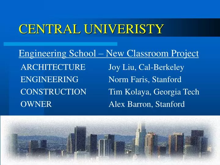
CENTRAL UNIVERISTY. Engineering School – New Classroom Project. ARCHITECTURE Joy Liu, Cal-Berkeley ENGINEERING Norm Faris, Stanford CONSTRUCTION Tim Kolaya, Georgia Tech OWNER Alex Barron, Stanford. Project Information. Central University Engineering School Location:

E N D
CENTRAL UNIVERISTY Engineering School – New Classroom Project ARCHITECTURE Joy Liu, Cal-Berkeley ENGINEERING Norm Faris, Stanford CONSTRUCTION Tim Kolaya, Georgia Tech OWNER Alex Barron, Stanford
Project Information • Central University Engineering School • Location: • Los Angeles Metropolitan Area • Busy urban location / heavy traffic • Seismic Concerns – San Andreas Fault (8 km)
SiteLocation • Site in San Francisco • Selected for accessibility by team 3rd Street & Folsom
Design Consideration Remote Team Work High Tech Neighborhood Seismic Urban Context Busy Traffic setting Warm Climate
Structural – Loading Conditions • Gravity • Live Loads(UBC) • Classroom / Offices = 50psf • Stairs/Corridors = 100psf • Auditorium seating = 50psf • Roof = 20psf • Dead Loads • Lightweight Composite Deck = 70psf • Concrete Slabs = 12psf/1” thickness • Flooring, ceiling and fixtures = 10psf • HVAC = 5psf • Partitions = 20psf • Exterior Cladding = 20psf (Vertical Surface) • Lateral • Seismic Conditions • Seismic Zone 4 • Soil Profile = SD • Near Source Effects • Occupancy Category = 1.0 • V = 0.205*W (Moment Frames) • V = 0.169*W (EBF) • Wind Loading • Design Wind Speed (70mph) = 20.2 psf
Construction Concerns • High Ground Water Level • Excavation/Shoring • Dewatering ~16 -20 Ft. • Los Angeles Traffic
Redesign • Ideas: “Sun Rise” • Explore the space from underground to top • Keep Circulation smooth • Think of the functionality of the space
Sun Rise • Old plan Cafe Gym New Plan Cafe Cafe Gym Basement 1st Floor 2nd Floor
Sun Rise • 3-D Model
Sun Rise – Structural Alternative 1 • Steel Moment Frames • Beams: W24 x 84 • Columns : W14x120 • Gravity System • Composite Slab (t = 6.5”) - W14 x 22 Beams • Columns: W12 x 50 In Context of Architectural Layout – 2nd Floor
Sun Rise – Structural Alternative 1 W12 Beams w/ 12” Channels @ Perimeter W18 Column Roof Opening Column to Mat Connection w/ Base Plate and Stiffener Beam to Concrete Wall w/ Embedded Plate and Studs LOBBY: RADIAL STEEL GRAVITY SYSTEM
Sun Rise – Structural Alternative 2 • Concrete Moment Frames • Beams: 18” x 24” • Columns : 18” x 18” • Gravity System • Post Tensioned (PT) Slab • Columns: 12” x 12” • Lobby – PT Column Beam System • Foundation System • 6’x6’ Spread Footings w/ 18” Grade Beams • 18” Post-Tensioned Mat Foundation below basement • 15” Retaining Wall
Sun Rise – Load Path (Alternative 1 & 2) • Lateral Loads • Distributed based upon rigidities • Rigid Floor Diaphragm • Gravity Loads • Post – Tension System: Slab – Column - Foundation • Composite Concrete & Steel System Deck – Beam – Girder – Column - Foundation
Sun Rise – Construction Schedule and Cost Breakdown Steel MRF w/ Composite Deck Concrete MRF w/ Post-Tensioned Deck Schedule Alt. 1 – 9 months Alt. 2 – 8 months Alt. 1 Alt. 2
Structural Design 1st Iteration Collaboration / Final Layout Attempt New Layout Adapt Old Design Updates Issues Concerns Revisions Initial Estimate Cost Concerns Detailed Estimate Sun Rise - Team Interaction
Architecture Vision of 2015 • Gaining awareness in Eco-design and sustainable architecture • Better and cheaper technology in day-lighting devices
New Design 1 - Square Plan • Design Concepts: • “Flying Eagle” In Southern Latitude: • Respond to orientation • Use Natural energy instead of artificial energy • Progression • Repetition of open and compressed space N
Flying Eagle • Model
Flying Eagle – Structural Alternative 1 • Steel Moment Frames • Beams: W24 x 84 • Columns : W18 x 211 • Gravity System • Composite Slab (t = 6.5”) w/ W12 x 26 Beams • Long Span Trusses @ 3rd Floor over Auditorium • Columns: W12 x 58 • Bending due to Lateral Loads induced in the Frame • Additional Bending in columns due to Cantilever Support System • Additional Costs to Reinforce Columns in their Weak Axis
Flying Eagle – Structural Alternative 2 • Lateral System • 2nd & 3rd Floors-Shearwall • t = 8” • Roof - Concrete MRF • Beams: 24” x 16” • Columns: 16” x 16” • Gravity System • 9” Flat Plate w/ Drop Beams 1st Floor Structural System in Context of Architectural Layout
Flying Eagle – Structural Alternative 3 • Concrete Moment Frame • Beams: 24” x 18” • Columns : 20” x 20” • Gravity System • 9” Flat Plate w/ Drop Beams between Columns • 24” Waffle Slab for 3rd floor above auditorium • Columns: 16” x 16” • Foundation System • 6’x6’ Spread Footings @ Columns • 15” Mat Foundation @ Basement Level • 4’ Continuous Footing @ Perimeter Walls • 12” Retaining Walls
Flying Eagle – Cantilever at 3rd Floor Composite Gravity System – Continuous From Main Structure TS Brace From Exterior Cantilever Columns to Frame W14 Column Struts – Welded at Frame & Connected to Column w/ Welded Base Plate
M.E.P System • Based upon 30,000 ft2 Floor Area • Cooling Capacity = 90 tons • Cooling Air Volume = 35000cfm • Total Space for Boiler Room and Chilled Water Plant = 600ft2 • Area of Main Supply or Return Ducts = 20ft2 • Area of Branch Supply or Return Ducts = 35ft2 • Area of Fresh Air Louvers = 80ft2 • Area of Exhaust Air Louvers = 70ft2 • All utilities localized at basement • Main Distribution Vertical • More Narrower Ducts • Single Excavation for Services • Centralized for efficiency
Flying Eagle – Construction Schedule and Cost Breakdown Shear Wall Concrete MRF Steel MRF Schedule Alt. 1 – 7½ months Alt. 2 – 8½ months Alt. 3 – 8 months Alt. 1 Alt. 2 Alt. 3
Flying Eagle - Team Interaction Structural Solution Propose Design Back to the Drawing Board – Revisions Finalize Design Issues Concerns Estimates/ Schedules Constraints / Constructability Structural Limitations Presented
New Design 2 - Diamond Plan • Idea: • “Pouring Stream” • The contrast of solid and void • Changes in experience • Bring the flow of vegetation to inside of the building • Recreation of Nature
Pouring Stream Old Plan New Plan
Pouring Stream Section
Pouring Stream • Material Choice • Exterior • Glass and lightweight metal with adjustable day-lighting metal panels. • Changes the personality of the building from day to night • Constant movement • Interior • Atria space will use wood(cladding) • Use concrete at other place. At Day At Night
Pouring Stream • Model
Pouring Stream – Structural Alternative 1 Steel Eccentric Brace Frame (EBF) w/ Composite Gravity System W21 x 62 Link Beam W21 ‘Outside’ Beam TS 6 X6 W12 Columns Link Beam w/ Stiffeners
Pouring Stream – Structural Alternative 1 3rd Floor Gravity System 6.5” Composite Deck w/ W12 x 26 Beams 24” Long Span Truss and Concrete Slab 8” Bearing Wall @ Elevator Shaft Cantilever Beam – Column at Central Atrium W12 x 50 Columns
Pouring Stream – Structural Alternative 2 • Steel SMRF w/ Shearwalls • Beams: W21 x 62 • Columns : W14 x 120 • Shearwall: 8” • Gravity System • Composite Deck(t=6.5) w/ W12 x 26 Beams • Columns: W12 x 50 In Context of Architectural Layout – 3rd Floor
Pouring Stream – Structural Alternative 3 • Concrete MRF w/ Shearwalls • Beams: 16” x 18” • Columns : 18” x 18” • Shearwall: 8” • Gravity System • 10” Flat Plate w/ Drop Beams • Columns: 12” x 12” Moment Frame Connection • Foundation System • 6’x 6’ Spread Footings • 4’ Cont. Footing @ Retaining Walls • 12” Mat Foundation @ Utility Tunnel • 12” Perimeter Retaining Wall
Pouring Stream – Construction Schedule and Cost Breakdown Steel EBF Steel SMRF Concrete MRF Schedule Alt. 1 – 8 months Alt. 2 – 8½ months Alt. 3 – 9 months Alt. 1 Alt. 2 Alt. 3
Pouring Stream - Team Interaction Structural Limitations Back to the Drawing Board – Revisions Propose Design Initial Estimate / Constructability Issues Cost Issues Finalize Design Structural Solutions Issues Concerns Estimates / Schedules
Equipment Selection • Hydraulic Truck Crane • Hydraulic Hammer • Backhoe Loader / Front-end Loader • Welding Machines • Cement Mixers / Dump Trucks / various others…
Original 2015 Budget Adjustment for Inflation Adjustment for Location - 1.1 New Adjusted Budget Sunrise - Alt. 1 Sunrise - Alt. 2 Flying Eagle - Alt. 1 Flying Eagle - Alt. 2 Flying Eagle - Alt. 3 Pouring Stream - Alt. 1 Pouring Stream - Alt. 2 Pouring Stream - Alt. 3 Budget Concerns • Construction in 2015 • Project Budget : $5.5 Million • Assumed 3.5% Inflation • Adjusted Budget : $3.4 Million • Cost Index for L.A. – 110%
Preferred Design Alternative ‘ POURING STREAM’ A: Effective Space Layout, Potential for Poetic Space, Good Eco-Design Development E: Steel SMRF w/ Shearwalls – Versatile – Efficient - Effective C: Within Budget and Schedule Constraints - Atrium Poses Interesting Challenge
Team Improvement • Team Dynamics • A interacts with owner the most • E is very good in informing A and C about his progress • C is very consistent in keeping group records, organization • Improvements • More interaction with Owner and Mentors • Inform each other about one’s progress more frequently • Continue education between three disciplines
Thank you! • We would like to pay our respect and gratitude to our mentors : • Brook Barrett - DPR • David Bendet -MBT • Eric Elsesser - Forell/Elsesser Engineers, Inc • Helmut Krawinkler – Stanford • Paul Chinowsky – Georgia Tech AND.. • Renate Fruchter - Stanford For contributing their valuable time and suggestions, Thank you!