Download
1 / 21
210 likes | 321 Views
Because of equipment availability, cost, and time, we will use aluminum as the top side conductor. Top Side Conductor vacuum deposition Aluminum sputter deposit in Argon plasma. CVC 601-sputter deposition tool.

E N D
Because of equipment availability, cost, and time, we will use aluminum as the top side conductor
Top Side Conductor vacuum deposition Aluminum sputter deposit in Argon plasma CVC 601-sputter deposition tool
A conductor metal is vacuum deposited on to the waferBecause of cost and equipment, aluminum will be used instead of silver Sputtered aluminum
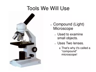
Photolithography • Photolithography is the transfer of patterns, circuits, device structures, etc. to a substrate or wafer using light and a mask or stencil to stop the light. • Photolithography is used extensively in the progression of microelectronics. • Today, because of the sizes involved in current computer microprocessor devices, other methods like direct patterning using electron beams are used. • Photolithography is still used for dimensions down to about 0.5um. The wavelength of UV light is .35-.45 um.
Top side conductor grid needs to be designed Pattern is created on a transparency sheet to keep cost low Once top side conductor grid is finalized, a chrome on glass professional mask can be made
Typical top side conductor Because of tester limitations (100mA) – cell size to be 10 cm2 max
UV light sensitive material called photoresist is spin coated on to the conductor side of he wafer
Wafers are spin coated with Shipley 1813 UV sensitive photoresistspin coating produces a uniform coating Spin speed is set here Light sensitive material is stored in amber dropper bottles – Use 1813 A vacuum chuck holds the wafer
Transparency is used as a photomask Cells can be of various sizes but must line up for saw cutting
The antenna design, arrayed on a transparency sheet, is placed on top of the wafer. This transparency is called a photo mask. Production photo masks would be made on glass plates with high precision patterns.
Ultraviolet light is projected down on to the photoresist coated wafer
HTG mask aligner and UV light sourceThe UV light source is a mercury vapor lamp at 436nm wavelength UV light with filter surrounding it Clear glass plates are used to make sure the transparency lays flat to the wafer Exposure time set on timer Wafer is held by vacuum, mask is placed on top and brought into contact with wafer
The wafer is developed, leaving photoresist where no UV light has penetrated the mask
Solitec automatic developer Vacuum switch Start switch
The conductor is disolved (etched) with the appropriate chemical
Aluminum is etched using the aluminum etchant at about 750C Aluminum etch
After etching, the top conductor grid pattern, will be left on the wafer Top conductor Top side conductor complete
Once the top side conductor grid is complete, the back side conductor can be deposited For this fabrication run, aluminum will also be sputtered as the back side contact
Assignment Complete your top side conductor grid pattern and submit