Download
1 / 1
10 likes | 119 Views
Automatic 3D Finite Element Mesh Generation : data fitting from an atlas Luboz Vincent*, Payan Yohan*, Swider Pascal**, Couteau Béatrice** *TIMC-IMAG Laboratory, GMCAO **INSERM, U518. Summary.

E N D
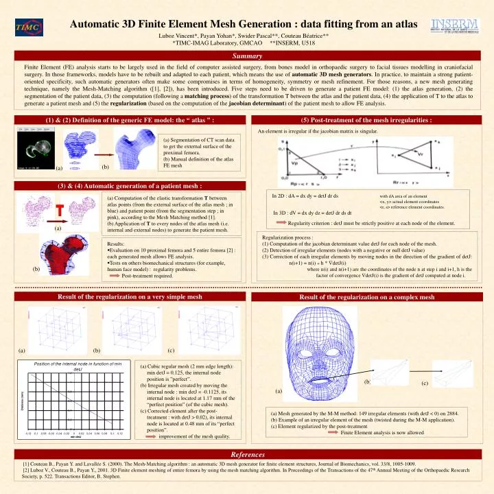
Automatic 3D Finite Element Mesh Generation : data fitting from an atlas Luboz Vincent*, Payan Yohan*, Swider Pascal**, Couteau Béatrice** *TIMC-IMAG Laboratory, GMCAO **INSERM, U518 Summary Finite Element (FE) analysis starts to be largely used in the field of computer assisted surgery, from bones model in orthopaedic surgery to facial tissues modelling in craniofacial surgery. In those frameworks, models have to be rebuilt and adapted to each patient, which means the use of automatic 3D mesh generators. In practice, to maintain a strong patient-oriented specificity, such automatic generators often make some compromises in terms of homogeneity, symmetry or mesh refinement. For those reasons, a new mesh generating technique, namely the Mesh-Matching algorithm ([1], [2]), has been introduced. Five steps need to be driven to generate a patient FE model: (1) the atlas generation, (2) the segmentation of the patient data, (3) the computation (following a matching process) of the transformation T between the atlas and the patient data, (4) the application of T to the atlas to generate a patient mesh and (5) the regularization (based on the computation of the jacobian determinant) of the patient mesh to allow FE analysis. (1) & (2) Definition of the generic FE model: the “ atlas ” : (5) Post-treatment of the mesh irregularities : An element is irregular if the jacobian matrix is singular. (a) Segmentation of CT scan data to get the external surface of the proximal femora. (b) Manual definition of the atlas FE mesh (b) (a) (3) & (4) Automatic generation of a patient mesh : In 2D : dA = dx dy = detJ dr ds with dA area of an element <x, y> actual element coordinates <r, s> reference element coordinates. In 3D : dV = dx dy dz = detJ dr ds dt Regularity criterion : detJ must be strictly positive at each node of the element. (a) Computation of the elastic transformation T between atlas points (from the external surface of the atlas mesh ; in blue) and patient point (from the segmentation step ; in pink), according to the Mesh Matching method [1]. (b) Application of T to every nodes of the atlas mesh (i.e. internal and external nodes) to generate the patient mesh. T (a) Regularization process : (1) Computation of the jacobian determinant value detJ for each node of the mesh. (2) Detection of irregular elements (nodes with a negative or null detJ value) (3) Correction of each irregular elements by moving nodes in the direction of the gradient of detJ: n(i+1) = n(i) + h * detJ(i) • where n(i) and n(i+1) are the coordinates of the node n at step i and i+1, h is the factor of convergence detJ(i) is the gradient of detJ computed at node i. Results: • Evaluation on 10 proximal femora and 5 entire femora [2] : each generated mesh allows FE analysis. • Tests on others biomechanical structures (for example, human face model) : regularity problems. Post-treatment required. (b) Result of the regularization on a very simple mesh Result of the regularization on a complex mesh (c) (a) (b) (a) Cubic regular mesh (2 mm edge length): min detJ = 0.125, the internal node position is ”perfect”. (b) Irregular mesh created by moving the internal node : min detJ = -0.1125, its internal node is located at 1.17 mm of the “perfect position” (of the cubic mesh). (c) Corrected element after the post-treatment : with detJ > 0.02), its internal node is located at 0.48 mm of its “perfect position”. improvement of the mesh quality. (b) (c) (a) (a) Mesh generated by the M-M method: 149 irregular elements (with detJ < 0) on 2884. (b) Example of an irregular element of the mesh (twisted during the M-M application). (c) Element regularized by the post-treatment Finite Element analysis is now allowed References [1] Couteau B., Payan Y. and Lavallée S. (2000). The Mesh-Matching algorithm : an automatic 3D mesh generator for finite element structures, Journal of Biomechanics, vol. 33/8, 1005-1009. [2] Luboz V., Couteau B., Payan Y., 2001.3D Finite element meshing of entire femora by using the mesh matching algorithm. In Proceedings of the Transactions of the 47th Annual Meeting of the Orthopaedic Research Society, p. 522. Transactions Editor, B. Stephen.