Download
1 / 121
1.21k likes | 1.41k Views
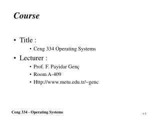
Course. 自动控制原理 I. School of Automation Southeast university. Any comments, please feel free to contact me ( 中心楼 621 , E-mail: jiangmin_57@tom.com ,Tel.: 83792418 (o)). 系统设计. Chap.6 系统校正方法. 6.1 引言. 控制理论的三部分内容:. 机理建模. 系统建模. 统计建模. 稳定性分析. 系统分析. 动静态性能分析. 结构分析 -state space.

E N D
Course 自动控制原理 I School of Automation Southeast university Any comments, please feel free to contact me (中心楼621, E-mail: jiangmin_57@tom.com ,Tel.:83792418(o)) Southeast University, Dept. of Automatic Control
系统设计 Chap.6 系统校正方法 6.1 引言 控制理论的三部分内容: 机理建模 系统建模 统计建模 稳定性分析 系统分析 动静态性能分析 结构分析-state space 综合(synthesis) -依据指标解析确定控制器 校正/补偿(compensation) Southeast University, Dept. of Automatic Control -依据期望指标,增加装置,改善开环特性
综合(synthesis)方法的特点 对于一个给定的控制系统(包括校正装置),首先找到一个能够满足给定指标的系统,然后计算所需要的校正装置或控制器。 对于结构不变的给定的控制系统,可以将性能指标转换成某个函数的优化问题,通过优化求解,得到参数最优化的控制系统。 Southeast University, Dept. of Automatic Control
综合方法示例 Southeast University, Dept. of Automatic Control
校正的意义 控制系统一般设计过程: 被控对象的机理建模(时域、频域)或统计建模。 根据工艺上对被控对象的参数及控制系统的任务和要求,确定控制系统的设计方案和结构,合理选择执行机构、功率放大器、检测元件等组成控制系统。 经过安装调试和运行,分析系统稳定性和各项动态、稳态性能指标。 若系统不满足要求,可以通过调整系统的参数或增加新的环节(校正)以改变系统传递函数使性能得到改善。 Southeast University, Dept. of Automatic Control
R(s) C(s) _ _ 校正装置的意义 1. 作用一:使闭环系统稳定。 2. 改善系统性能. (a) 仅靠调整系统参数使系统满足工程要求是困难的。 例:改善二阶系统阻尼 (b)增加新的装置/环节,从而改变系统原有结构(传函),是改善系统性能的主要手段 Southeast University, Dept. of Automatic Control
一、性能指标 • 不同的控制系统对性能指标的要求应有不同的侧重。 • 如调速系统-平稳性和稳态精度;随动系统-快速性 • 性能指标的提出,应符合实际系统的需要和可能(代价) 。 • 性能指标: 静态指标 时域指标(根轨迹法) 动态指标 频域指标(频域法) 开环频域指标 闭环频域指标: 例如,带宽 Southeast University, Dept. of Automatic Control
二 阶 系 统 的 指 标 Southeast University, Dept. of Automatic Control
高阶系统性能指标的经验公式 Southeast University, Dept. of Automatic Control
R(s) C(s) _ _ 二、校正方式 常见校正方式:串联校正,反馈校正,前馈校正,复合校正 Southeast University, Dept. of Automatic Control
对系统闭环极点的要求 Southeast University, Dept. of Automatic Control
三、校正的特点和难点 校正设计的非惟一性。 (不同校正方法,同一种方法的多种实现) 校正设计的试凑,经验性。 校正装置实现的非惟一性。 (机电,液压,气动,有源,无源等) Southeast University, Dept. of Automatic Control
6.2 系统校正的根轨迹法 6.2.1 增加零极点对根轨迹的影响 一、增加极点的影响 在开环系统中增加极点,可以使根轨迹向右方移动,从而降低了系统的相对稳定性,增加系统响应的调节时间。 Southeast University, Dept. of Automatic Control
二、增加零点的影响 在开环系统中增加零点,可以使根轨迹向左方移动,从而增加系统的相对稳定性,减小系统响应的调节时间。 。 Southeast University, Dept. of Automatic Control
三、增加原点附近开环偶极子对根轨迹的影响 偶极子是指开环系统中相距很近(和其它零极点相比)的一对极点和零点。 偶极子对系统的稳定性和动态性能几乎没有影响。 根轨迹解释:模条件和相角条件的相互抵消性。 在原点附近?增加开环偶极子,可提高系统的开环增益,改善静态特性。 Southeast University, Dept. of Automatic Control
四、基于根轨迹校正的一般步骤 1、根据给定的动态性能指标确定主导极点的位置。 2、绘制未校正系统的根轨迹,若希望主导极点不在此根轨迹上,说明仅靠调整系统增益不能满足性能要求,增加校正装置改造系统根轨迹。 3、当校正后的根轨迹已通过希望的主导极点时,还需要检验相应的开环比例系数是否满足静态性能要求。若不满足,可采用在原点附近增加开环偶极子的办法来调节开环比例系数,同时保持根轨迹仍通过希望的主导极点。 Southeast University, Dept. of Automatic Control
6.2.2 根轨迹校正举例 一、超前校正 常用于系统稳态特性已经满足,而瞬态性能差的场合 Southeast University, Dept. of Automatic Control
例 6.1 根轨迹校正举例 设计串联校正环节,使校正后%30%,ts2s,K05 Southeast University, Dept. of Automatic Control
例 6.1 -3.4 不满足 主导极点条件?(P.240) 满足系数小条件-主导极点条件!(P.240) 30度超前角条件解不惟一,可以使增加的零点和极点离虚轴足够远。 Southeast University, Dept. of Automatic Control
例 6.1 Southeast University, Dept. of Automatic Control
Answer 2 of 例 6.1 -18 Southeast University, Dept. of Automatic Control
例 6.1 Southeast University, Dept. of Automatic Control
6.2.2 根轨迹校正举例 二、滞后校正-开环偶极子 常用于系统已具有满意的动态性能指标,但其稳态性能不符合要求的场合 Southeast University, Dept. of Automatic Control
6.2.2 根轨迹校正举例 例6.2设计串联校正环节使闭环主导极点=0.5,n0.6,Kv5 Southeast University, Dept. of Automatic Control
例6.2 Southeast University, Dept. of Automatic Control
例6.2 Southeast University, Dept. of Automatic Control
6.2.2 根轨迹校正举例 超前校正可以改善系统的瞬态性能,提高系统的相对稳定性; 滞后校正可以改善系统的稳态性能,增大系统的开环比例系数。 三、滞后—超前校正 常用于对系统的动态特性和稳态特性都有较高要求的场合 Southeast University, Dept. of Automatic Control
滞后—超前校正设计步骤 1、根据给定的性能指标,确定希望的主导极点sd的位置。 2. 计算当主导极点位于希望位置时,相角的缺额 3、相角缺额由校正装置中的超前部分承担 4、利用模条件确定校正环节的增益的值 5. 根据稳态性能公式确定滞后校正装置增益放大倍数 6.在原点附近选择开环偶极子 Southeast University, Dept. of Automatic Control
6.2 系统校正的根轨迹法 6.2.3 校正装置的实现 一、超前校正 Southeast University, Dept. of Automatic Control
一、超前校正 无源网络的实现和应用限制 Southeast University, Dept. of Automatic Control
二、滞后校正装置 Southeast University, Dept. of Automatic Control
二、滞后校正装置 无源网络的实现 Southeast University, Dept. of Automatic Control
三、滞后—超前校正装置 Southeast University, Dept. of Automatic Control
C1 R 1 R u u 2 c r C2 + + ( T s 1 )( T s 1 ) 1 2 = G ( s ) c T 1 + + ( aT s s 1 ) 1 ( 2 a ) 三、滞后—超前校正装置 无源网络的实现 Southeast University, Dept. of Automatic Control
Chap.6 系统校正方法 6.3 系统校正的频率响应法 6.3.1 开环频率特性与时域性能指标间的关系 频率特性的低频段表征了系统的稳态性能(s=jw→0) 中频段表征了系统的动态性能 高频段则反映了系统的抗高频干扰的能力 Southeast University, Dept. of Automatic Control
6.3.1 开环频率特性与时域性能指标间的关系 一、低频段(0) 根据低频段特性易确定开环系统增益和型别 Southeast University, Dept. of Automatic Control Ⅱ型系统?
6.3.1 开环频率特性与时域性能指标间的关系 二、中频段 中频段是在截止频率附近区段,其斜率和宽度反映系统动态响应的平稳性和快速性 以最小相位系统为例 1、中频段幅频特性的斜率 好性能:-20dB/dec过截止频率 Southeast University, Dept. of Automatic Control
6.3.1 开环频率特性与时域性能指标间的关系 二、中频段 2、截止频率与通频带宽 截止频率c越大,通频带宽b越大,复现输入程度高 c过大,高频噪声 也被放大 3、相角裕度与动态性能 相角裕度很小,易产生谐振 Southeast University, Dept. of Automatic Control
6.3.1 开环频率特性与时域性能指标间的关系 三、高频段 >10c , L()分贝值越低,抗高频噪声的能力越强. Southeast University, Dept. of Automatic Control
6.3 系统校正的频率响应法 6.3.2 频率特性法校正举例 一、超前校正 Southeast University, Dept. of Automatic Control 通常取0.05→最大相位超前大约为65度
6.3.2 频率特性法校正举例 超前校正装置特点: • 高通滤波器,会增大开环截止频率和系统带宽 • 开环系统幅频特性在m处提高幅值 • 通常将m选在c附近,使系统的相角裕度增大,改善系统动态. Southeast University, Dept. of Automatic Control
串联超前校正的一般步骤 1.根据稳态误差的要求,确定校正装置Kc画出未校正系统 KcP(j )的Bode图 2.计算未校正系统的相角裕度,判断是否需用超前校正 3.根据动态性能指标选择截止频率,计算超前网络参数和T 关键是选择 以保证系统的响应速度,并充分利用装置的相角超前特性。 4、验算校正后的相角裕量和增益裕量 Southeast University, Dept. of Automatic Control 法2: 求也可根据最大超前角公式
例6.3:单位反馈系统的开环传递函数为: 设计要求:(1)系统在单位斜坡输入作用下,稳态误差≤ 0.1 ; (2)开环截止频率ωc≥4.4rad/s ; (3)相角裕度γ≥45°; (4)幅值裕度Lg≥10dB ; 试设计校正装置。 (1) Kv=10 (2) ’c=3.1<4.4, γ’=17.9o (3)取c=4.4, L(c)=20lg10-40lg4.4=-5.7 Southeast University, Dept. of Automatic Control
(1)系统在单位斜坡输入作用下,稳态误差≤ 0.1 ; (2)开环截止频率ωc≥4.4rad/s ;(3)相角裕度γ≥45°; (4)幅值裕度Lg≥10dB ; w dB 校正后c=4.4 L ( ) - 20 20 8.5 w 1 0.1 10 2.3 - 40 j w ( ) γ=48.2 0 w o - 90 o - 180 裕度Lg无穷大 Southeast University, Dept. of Automatic Control
例6.3:单位反馈系统的开环传递函数为: (1)系统在单位斜坡输入作用下,稳态误差≤ 0.1 ; (2)开环截止频率ωc≥4.4rad/s ;(3)相角裕度γ≥45°; (4)幅值裕度Lg≥10dB ; (1) Kv=10 (2) ’c=3.1<4.4, γ’=17.9o (3)取c=4.4, L(c)=20lg10-40lg4.4=-5.7 Southeast University, Dept. of Automatic Control
(1)系统在单位斜坡输入作用下,稳态误差≤ 0.1 ; (2)开环截止频率ωc≥4.4rad/s ;(3)相角裕度γ≥45°; (4)幅值裕度Lg≥10dB ; w dB L ( ) 校正后c=4.4 - 20 20 7.9 w 1 0.1 10 2.4 γ=45 ° j w ( ) - 40 0 w o - 90 裕度Lg无穷大 o - 180 Southeast University, Dept. of Automatic Control