Download
1 / 37
370 likes | 402 Views
Chapter 9 Interference February 4 General considerations of interference 9.1 General considerations Introduction : Wave equation Superposition principle

E N D
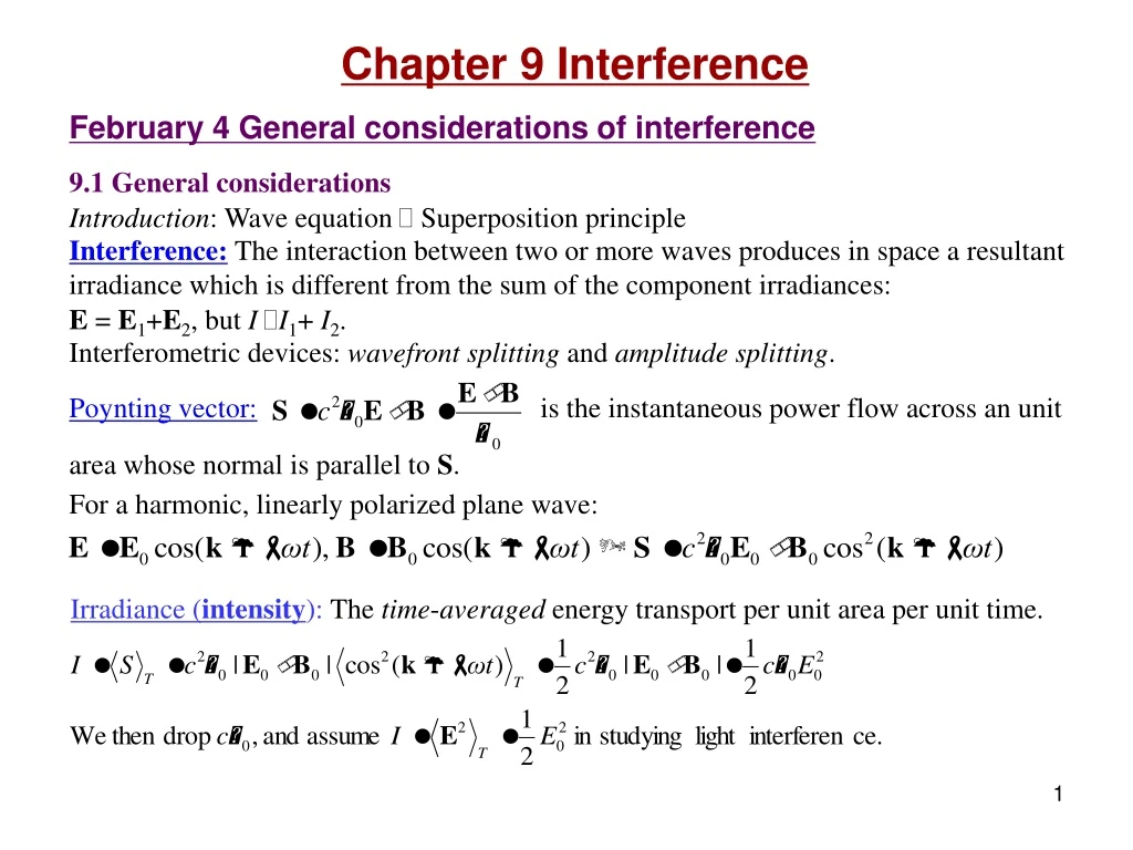
Chapter 9 Interference February 4 General considerations of interference 9.1 General considerations Introduction: Wave equation Superposition principle Interference:The interaction between two or more waves produces in space a resultant irradiance which is different from the sum of the component irradiances: E = E1+E2, but I I1+ I2. Interferometric devices: wavefront splitting and amplitude splitting. Poynting vector:is the instantaneous power flow across an unit area whose normal is parallel to S. For a harmonic, linearly polarized plane wave: Irradiance (intensity):The time-averaged energy transport per unit area per unit time.
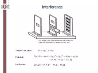
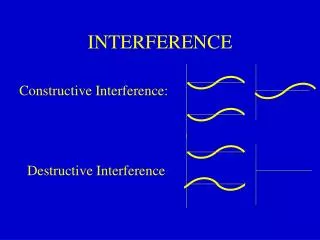
Superposition of two planar, linearly polarized waves (vector model): Phase difference interference term • When E01 and E02 are perpendicular, I12=0, no interference. • When E01 and E02 are parallel, Note that cosd averages to 0 in space: energy is conserved.
Total constructive interference: Total destructive interference: When I1=I2=I0, Interference fringes between two plane-waves: Bright fringes: k1 d k1-k2 q k2 Fringes are parallel planes perpendicular to k1-k2 . Exercise: Prove that the distance between the interference planes is Hint: Discussion: Fabrication of photographic gratings.
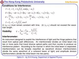
9.2 Conditions for interference • For producing stable patterns, the two sources must have the same frequency. • For producing interference patterns, the two fields must have parallel components. • For producing clear patterns, the two sources must have similar amplitude. • For producing interference patterns, coherent sources are required. =Relative phase predictable Temporal coherence: Coherence time: Time interval Dtc in which the light resembles a sinusoidal wave. (~10 ns for quasi- monochromatic light sources.) Coherence length: Dlc= cDtc. Relation to bandwidth (uncertainty principle): DnDtc1. Useful relations: Spatial coherence: The correlation of the phase of a light wave between different spatial locations. Depends on the size of the light source.
Read: Ch9: 1-2 Homework: Ch9: 2,3 Due: February 15
P r1 r2 S1 S2 m=-1 0 +1 P r1 r2 S1 S2 February 6 Interference of spherical waves Superposition of two spherical waves: At a far field, I1I2I0. Maximum: Minimum: Hyperboloids a m = M Interference patterns: • Viewing screen perpendicular to the S1-S2 axis: Concentric Rings. • Viewing screen parallel to the axis: Parallel fringes (Young’s experiment). • Maximum order of rings: -M< m <M, where M =a/l. (-a <r1-r2 <a)
m=-1 0 +1 P r1 r2 S1 S2 Variation of the interference rings: When reducinga : • The rings swallow. (What we observe in the Michelson interferometer.) • The distances between adjacent rings at a fixed viewing point increases. a m = M Superposition of a plane wave and a spherical wave: Move S1 to infinity.
m=-1 0 +1 P r1 r2 S1 S2 (*Reading) Bisector theorem of interference planes : Theorem: For the interference of two spherical waves, the local interference plane bisects the rays from the two sources. The local distance between the interference planes is where q is the angle between the two rays. a m = M
(*Reading) Size of the interference rings: P r1 (xn) xm r2 S1 S2 v u Note: • The size of the nth ring from the center: • S1, S2 and the viewing screen form a lens system: • Distance between rings: • For interference between a plane wave and a spherical wave:
(*Reading) Interference pattern and holography: • Two coherent waves produce an interference pattern. • The interference pattern is photographically recorded, which makes a hologram. • Now remove one of the waves (called the object wave), and illuminate the hologram with the other wave (called the reference wave). The removed wave is then magically reproduced in space! A B A Reconstruction Record
Read: Ch9: 1-2 No homework
a s ay/s February 8 Wavefront-splitting Interferometers 9.3 Wavefront-splitting interferometers 9.3.1 Young’s experiment (1801) Young’s originality: Obtaining spatially coherent light from a pinhole, and splitting the wavefront of the spatially coherent light with two pinholes. Optical path difference: r2 – r1 = a sin θ = ay/s ( If s>>a, s>>y ) Positions of bright fringes: m = 0, ±1, ±2, … is the order number. L Distance between fringes: Intensity distribution of the fringes:
A P B lc A' B' r2 – r1 Shield S P M1 r1 S1 y a s r2 M2 S2 Effects of finite coherence length: • Light from each slit has a coherence length lc. For sunlight (blackbody) lc3l. • The waves from two slits can only interfere if r2 – r1 <lc. • The contrast of the fringes degrades when the amount of the overlap between uncorrelated wavegroups increases. Other wavefront-splitting interferometers Fresnel’s double mirror: Slits S1 and S2 act as virtual coherent sources. They are images of slit S inthetwomirrors. L= r2 – r1 Space between fringes:
S1 q a S S2 y S a s S' Fresnel’s double prism: Interference between light refracted from the upper and the lower prisms. The prisms produce two virtual coherent source S1 and S2. Question: Where are S1 and S2? Lloyd’s mirror: Interference between light from source S and its image S ' in the mirror. Glancing incidence causes a phase shift of p, therefore the fringes are complementary to those of Young’s. Example 9.1
Read: Ch9: 3 Homework: Ch9: 6,20,23,27 Due: February 15
P S qi D n1 A C d qt nf B n2 February 11 Amplitude-splitting Interferometers-1 9.4 Amplitude-splitting interferometers 9.4.1 Dielectric films – double-beam interference Application: Optical coating reduces or enhances the reflection of optical devices through thin-film interference effects. Fringes of equal inclination Consider the first two reflections (other reflections are weak if the reflectance is not large). Optical path length difference:
Phase shift in reflections when the angle of incidence is small: Erp Eip kr Eis Ers ki qi qr ni nt Ets qt 1) External reflection, ni<nt . There is a phase shift of p between the incident electric field and the reflected electric field. 2) Internal reflection, ni>nt . There is no phase shift between the incident electric field and the reflected electric field. Etp kt
Phase difference: Assume nf >n1, nf >n2. There is a phase shift of p between external and internal reflections (when the incident angle is not large). Bright spot: Dark spot: Extended source: All rays inclined at the same angle arrive at the same point. Fringes of equal inclination: Arcs centered on the perpendicular from the eye to the film (where qi=0). Haidinger fringes:The fringes of equal inclination viewed at nearly normal incidence. • Concentric circular bands. Example 9.4, 9.5
Read: Ch9: 4-5 Homework: Ch9: 35,38,41,42,44,46 Due: February 22
n1 nf a n2 x February 13 Amplitude-splitting Interferometers-2 Fringes of equal thickness Fizeau fringes: Contours from a non-uniform film when viewed at nearly normal incidence. Thickness of a wedge: d = a x Interference maximum: d Compare: For the interference between two plane waves, the distance between the fringe planes is Example 9.6
x d Newton’s rings: Interference pattern from an air film between two glass surfaces. Thickness: Bright rings: 2nf dm = (m + ½)l, Dark rings: Discussions:Fabricating zone plates. Example 9.7
Single-layer antireflection coating: • In order to let the two reflected light waves cancel each other, we need • The two reflected waves has a phase shift or p : • The amplitudes of the two reflected waves are nearly equal: air film substance Example 9.8
Beam splitter Movable mirror S2 S1 S q 2dcosq P Optical path length difference: Phase difference: Dark fringes: M1 M2 9.4.2 Mirrored interferometers Michelson interferometer • Compensation plate: Negates dispersion from the beam splitter • Collimated source: Fringes of equal thickness • Point source: Interference of spherical waves • Extended source: Fringes of equal inclination S p from the splitter. Application: Accurate length measurement. Example 9.9
*Reading: Interference colors When a white light source is used in an interference experiment, each spectral component will produce its own interference pattern in space. The overlapped interference patterns from all spectral components result in the appearance of a special sequence of colors. Calculated interference colors Crossed polarizers Parallel polarizers • Examples: • Soap bubbles • Oil films • Thin film coatings • Crystals between polarizers • Applications: • Identify minerals • Control coatings • Inspect strains
Read: Ch9: 4-5 No homework
S qi nf d qt February 15,18 Multiple beam interference 9.6 Multiple beam interference Interference between multiple reflection and refractions: Reduces to fringes of equal inclination when r is small.
Coefficient of finesse: Airy function: F = 0.2 (r2 = 0.046) F = 1 (r2 = 0.17) F = 200 (r2 = 0.87)
P S d 9.6.1 The Fabry-Perot interferometer • High resolving power • Prototype of laser cavity Half-width of transmission: Finesse:
Applications: I. How a laser wavelength is selected. 1) The laser itself is a Fabry-Perot cavity. Two highly reflective mirrors select an output of a certain wavelength with an extremely narrow bandwidth, which is called a mode. 2) The mode separation in a laser cavity (Dn=c/2l) can be smaller than the gain profile of the laser medium, therefore output of multiple modes is possible. 3) Laser modes can be longitudinal or transverse.
II. How a scanning spectrum analyzer works. • A scanning spectrum analyzer can be used to study the output modes of a laser. • 2) The analyzer is a Fabry-Perot interferometer whose length can be slightly varied by a piezoelectric device. • 3) A saw-tooth voltage is used to repeatedly change the cavity length, and the output signal is displayed on an oscilloscope. scanning scanning
1 tt' r r r2 qi qr ni nt rt qt t tr' t
Read: Ch9: 6 Homework: Ch9: 50,53,54,56 Due: March 1
February 20 Multilayer coatings 9.7 Applications of single and multilayer films Relations between the E and H-fields at the two surfaces of a single layer coating: s-polarization: Boundary conditions (tangential parts of the E and H-fields): × × × × × × qiI n0 I × n1 qiII d II ns
For multiple layer coatings: Amplitude coefficients of reflection and transmission:
Antireflection coatingsat normal incidence: Reflectance:
Read: Ch9: 7 Homework: Ch9: 57,59,61 Due: March 1
Tout le malheur des hommes vient d’une seule chose, qui est de ne savoir pas demeurer en repos dans une chambre. All men's miseries derive from not being able to sit in a quiet room alone. Blaise Pascal