Download
1 / 36
360 likes | 491 Views
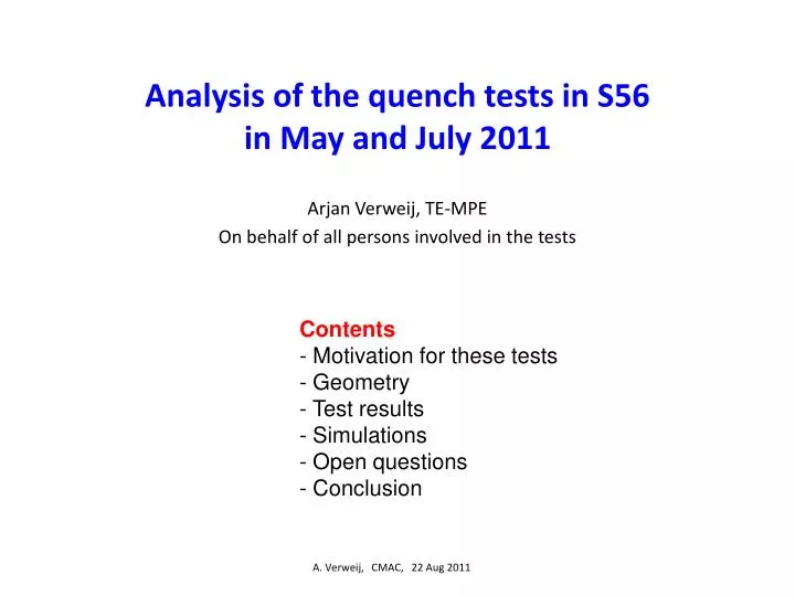
Analysis of the quench tests in S56 in May and July 2011. Arjan Verweij, TE-MPE On behalf of all persons involved in the tests. Contents - Motivation for these tests - Geometry - Test results - Simulations - Open questions - Conclusion. A. Verweij, CMAC, 22 Aug 2011. Motivation.

E N D
Analysis of the quench tests in S56 in May and July 2011 Arjan Verweij, TE-MPE On behalf of all persons involved in the tests Contents - Motivation for these tests - Geometry - Test results - Simulations - Open questions - Conclusion A. Verweij, CMAC, 22 Aug 2011
Motivation During the Chamonix 2009 workshop it was pointed out that a 13 kA joint could burn-out in case of a quench, if there would be a bad bonding between the cable and the copper bus coinciding with a discontinuity in the copper stabiliser. Since then, resistance measurements and -ray pictures have shown the presence of many of such defective joints in the machine, limiting the safe operating current to about 6 kA. A. Verweij, CMAC, 22 Aug 2011
During the Chamonix 2011 workshop it was shown that the largest probability to quench a joint was caused by thermal propagation of the heat developed in the magnet and the diode by-pass. It was therefore concluded to remain at 3.5 TeV in 2011. It was also recommended to measure this propagation in the machine. Spurious trips/heater firings, …. Training Beam losses Cable/bus movement Resistive losses in the splice Prompt quench of a joint Thermal propagation through the bus Quench of a magnet Delayed quench of a joint Thermal propagation through GHe Burn-out of the joint A. Verweij, CMAC, 22 Aug 2011
Geometry Typical powers at 6 kA: Diode: 6 kW Diode busbars: 2x25 W Contacts: 200 W (assuming 2x3 mW) I Magnet (1.8 MJ @ 6 kA) Magnet (1.8 MJ @ 6 kA) Joint I ‘heat sink’ contacts ‘half moon’ contacts Diode Diode A. Verweij, CMAC, 22 Aug 2011
Geometry 21 cm Main busbars RB joint Upper diode busbar (partially flexible) ‘Half moon’ contact towards diode
The diode Rc,moon Lower diode busbar Diode box, Helium contents : 5 liter Reception tests in FRASCATI: Endurance tests: 10 current cycles with 13 kA, t=120 s. The diode voltage and Rc,diode were measured. Rc,hs has only been checked a few times. Cold reception tests (in SM18): Each diode has only experienced one current pulse below 1 kA for less than 1 s. Rc,hs+Rc,moon has been measured during this transient and was always below 5 mW. Upper heat sink Rc,hs Rc,diode Lower heat sink A. Verweij, CMAC, 22 Aug 2011
Contents: • Motivation for these tests • Geometry • Test results • Measured magnets • Forward voltage over the diodes • Propagation into the bus • Voltage & resistance in the diode leads • Simulations • Open questions • Conclusion A. Verweij, CMAC, 22 Aug 2011
Measured magnets All numbers in kA 6 magnets from stable part of production 3 magnets with training 3 magnets without training Total: 28 heater induced quenches A. Verweij, CMAC, 22 Aug 2011
Test results Measured magnets Forward voltage over the diodes Propagation into the bus Voltage & resistance in the diode leads I Magnet (1.8 MJ @ 6 kA) Joint I Udiode Diode A. Verweij, CMAC, 22 Aug 2011
Diode voltages for 6 kA quenches Conclusion: Forward voltage (and hence the heating) over the 6 diodes is very uniform. (s<10 mV) Diode cooling down Diode blocks Magnet not yet fully s.c., all current in magnet Magnet s.c., all current in magnet, U=L*dI/dt A. Verweij, CMAC, 22 Aug 2011
Test results Measured magnets Forward voltage over the diodes Propagation into the bus Voltage & resistance in the diode leads To next magnet Ubus I Ubus Magnet (1.8 MJ @ 6 kA) To next magnet Joint I Diode A. Verweij, CMAC, 22 Aug 2011
Propagation towards the joint at 6 kA magnet quench Conclusion: Propagation in 5 out of 12 busses. The joint does not quench, but at higher currents many joints will. Assuming RRR=250 A. Verweij, CMAC, 22 Aug 2011
Test results Measured magnets Propagation into the bus Forward voltage over the diodes Voltage & resistance in the diode leads I Magnet (1.8 MJ @ 6 kA) Joint I Ulead,A Diode Ulead,C
Diode lead ‘resistances’ for 6 kA quenches Conclusion: Large spread among the 12 leads. ‘Steps’ occurring in first 15 s. 5 mW: maximum measured at reception in SM18 13 mW: specification during reception in SM18
Diode lead ‘resistances’ for B15R5 Anode Conclusion: Inductive signal is small. Results indicate the presence of one or more irregular contacts. The three 6 kA curves differ a factor 2.
Summary C=Cathode, A=Anode, Resistances in mW Rcold: resistance measured during cold reception in SM18 Conclusion: There is no correlation between diode lead resistance and propagation into the bus. A. Verweij, CMAC, 22 Aug 2011
Contents: • Motivation for these tests • Geometry • Test results • Simulations • Open questions • Conclusion A. Verweij, CMAC, 22 Aug 2011
Simulations Simulations are performed using the codes Comsol and QP3, giving very similar results. Comsol output for the final temperature after a 6 kA quench with zero contact resistances (adiabatic conditions) 95 K 50 K 60 K A. Verweij, CMAC, 22 Aug 2011
Comsol output for the final temperature after a 6 kA quench with Rc,moon=40 mW (adiabatic conditions) 90 K 180 K 95 K A. Verweij, CMAC, 22 Aug 2011
Contents: • Motivation for these tests • Geometry • Test results • Simulations • Open questions concerning the high resistances in the diode leads: • Do the resistances increase/decrease with the number of current pulses? • Is there a correlation with current? • Are these values dangerous for 12 kA operation? • 3) Where is this large contact resistance? • Conclusion A. Verweij, CMAC, 22 Aug 2011
Do the resistances increase/decrease with the number of current pulses? Conclusion: The behaviour with number of current pulses is irregular A. Verweij, CMAC, 22 Aug 2011
Is there a correlation with the current? Conclusion: There is an average trend that the resistance increases with current. A. Verweij, CMAC, 22 Aug 2011
Are large resistances dangerous for operation at 12 kA, t=100s? Cooling to helium is disregarded The maximum temperatures are lower if the excess resistance is located at the bolted contact with the heat sink. Conclusion: Resistances above 20 mW are worrying, especially if the resistance is in the half moon. A. Verweij, CMAC, 22 Aug 2011
Where is the large contact resistance? Simulations show that a large Rc,moon should cause thermal propagation into the main bus. However the measurements do not show a correlation between the diode lead voltage and the propagation. Rc,moon Conclusion: the largest contribution is most likely located at Rc,hs, but more tests are needed to validate this. Rc,hs Rc,diode This contact was accurately monitored during the reception tests in FRASCATI, and was very small and became even smaller with number of current pulses. A. Verweij, CMAC, 22 Aug 2011
Several tests are planned to find out what is happening • Cold tests in SM18 on several diodes (end 2011) • As similar as possible to the machine but with additional instrumentation. • Currents up to 12 kA. • 3rd series of quench tests in the machine (Sept 2011) • Quenches at 2-6 kA on 4 quadrupole apertures. • Warm tests on a few diodes (Aug 2011) • Small current (10-100 A). • Applying a force on the diode bus bar simulating the Lorentz force in the machine. • Tests in SM18 on a dipole + diode (2012) A. Verweij, CMAC, 22 Aug 2011
Conclusion (1/2) • Diode voltages: • As expected. • Opening and forward voltages among the diodes are very uniform. • Propagation into the bus: • Observed at 6 kA for 5 out of the 12 leads. At 5 kA for 1 out of 6. • Running at 3.5 TeV is a bit more safe than presented in Chamonix 2011. • It is rather sure that at currents >7 kA a magnet quench will almost always propagate to the closest 13 kA joint. • No quenches in the bus have been observed at 6 kA due to propagation of ‘warm’ helium gas. A. Verweij, CMAC, 22 Aug 2011
Conclusion (2/2) • Diode lead voltages/resistances: • The measured resistances (up to 50 mW) are much larger than measured during the cold reception in SM18 (<5 mW) and in many cases much larger than specified during production (<13 mW). The results suggest the presence of irregular contacts. • The variation among the 12 measured diode leads is very large, and even larger resistances may be present in the other 4000 diode leads of the LHC. • Resistances >20mW are worrying for safe operation at 12 kA, t=100 s especially if this resistance is in the ‘half moon’. The large excess resistance measured is probably at the heat sink, since no correlation is observed between propagation and the voltage in the diode lead. Note also that we have not experienced any problem with the high current training quenches during the 2008 hardware commissioning. • Several experiments are proposed to better understand the origin of the large increase in resistance and the correlation with current. • The CSCM (see next talk) during the X-mas shut-down could offer a unique occasion to map the resistance of all the diode leads at 6 kA. A. Verweij, CMAC, 22 Aug 2011
Annex slides if needed A. Verweij, TE-TM, 16 Aug 2011
Temperature increase heat sink (6 kA, tau=50 s, no cooling)
BB2 BB4 EE015 EE014 HM4 HM3 UM2 Zoom for B15R5
RC,diode (Contact resistance between diode and heat sink. Spec.: <5 mW)
Upper diode busbar Lyra Main RB bus RB joint A. Verweij, CMAC, 22 Aug 2011
Lorentz force between the diode leads at 6 kA 30 N 20 N 10 N 70 N A. Verweij, CMAC, 22 Aug 2011
Reliability of power connections M. Braunovic J Zhejiang UnivSci A 2007 8(3):343-356
Melting points: Cu: 1357 K Ni: 1726 K Reliability of power connections M. Braunovic J Zhejiang UnivSci A 2007 8(3):343-356