Download
1 / 86
860 likes | 1.12k Views
CS147. T,JK-flip-flop, Midterm 1 Revision Decoders and Multiplexers. Lecture 9. Prof. Sin-Min Lee Department of Computer Science San Jose State University. 4 Basic types of Flip-Flops. SR, JK, D, and T JK ff has 2 inputs, J and K need to be asserted at the same time to change the state

E N D
CS147 T,JK-flip-flop, Midterm 1 RevisionDecoders and Multiplexers Lecture 9 Prof. Sin-Min Lee Department of Computer Science San Jose State University
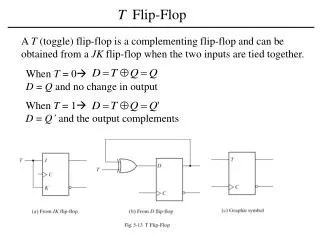
4 Basic types of Flip-Flops • SR, JK, D, and T • JK ff has 2 inputs, J and K need to be asserted at the same time to change the state • D ff has 1 input D (DATA), which sets the ff when D = 1 and resets it when D = 0 • T ff has1 input T (Toggle), which forces the ff to change states when T = 1 • SR ff has 2 inputs, S (set) and R (reset) that set or reset the output Q when asserted
Analysis of Sequential Systems • Goal: • Decide the timing and functional behavior from the implementation of a sequential system composed of FFs and logic gates • Types: • Functional analysis • Timing analysis
The origin of the name for the JK flip-flop is detailed by P. L. Lindley, a JPL engineer, in a letter to EDN, an electronics newsletter. The letter is dated June 13, 1968, and was published in the August edition of the newsletter. In the letter, Mr. Lindley explains that he heard the story of the JK flip-flop from Dr. Eldred Nelson, who is responsible for coining the term while working at Hughes Aircraft. Flip-flops in use at Hughes at the time were all of the type that came to be known as J-K. In designing a logical system, Dr. Nelson assigned letters to flip-flop inputs as follows: #1: A & B, #2: C & D, #3: E & F, #4: G & H, #5: J & K. Given the size of the system that he was working on, Dr. Nelson realized that he was going to run out of letters, so he decided to use J and K as the set and reset input of each flip-flop in his system (using subscripts or somesuch to distinguish the flip-flops), since J and K were "nice, innocuous letters."
Dr. Montgomery Phister, Jr., an engineer under Dr. Nelson at Hughes, picked up the idea that J and K were the set and reset input for a "Hughes type" of flip-flop, which he then termed "J-K flip-flops," a name that he carried with him when he left for Scientific Data Systems in Santa Monica.
Implement D Flip-flop by T Flip-flop Q Q 0 1 0 1 D T 0 1 0 1 0 1 0 0 1 0 1 1 T = D Q’ + D’ Q D D’ T
Implement JK Flip-flop by D Flip-flop Q Q 0 1 0 1 J K J K D Q+ 0 0 0 1 1 1 1 0 • 0 1 • 0 0 • 0 • 1 1 0 0 0 1 1 1 1 0 • 0 1 • 0 0 • 0 • 1 1 0 1 0 1 D = J Q’ + K’ Q Q J D K Q’
Implement JK Flip-flop by T Flip-flop Q+ Q Q 0 1 0 1 J K Q+ J K J K T Q+ 0 0 0 1 1 1 1 0 • 0 1 • 0 0 • 0 • 1 1 0 0 0 1 1 1 1 0 • 0 0 • 0 1 • 1 • 1 0 0 0 0 1 1 0 1 1 Q 0 1 Q’ Q Q’ 0 1 T = J Q’ + K Q Q J T K Q’
Implement T Flip-flop by JK Flip-flop Q T 0 1 J K Q Q+ 0 1 1 0 0 1 0 0 0 1 1 0 1 1 0 X 1 X X 1 X 0 Q Q T 0 1 T 0 1 X 0 X 1 0 X 1 X 0 1 0 1 K = T J = T
F = Σm F = ΠM = xy = (x+y)(x+y´)(x´+y) (x+y)(x+y´)(x´+y) = (x+(y.y´))(x´+y) = (x+0) (x´+y) = x.x´+xy = 0+xy = xy
Example • F(X,Y,Z) = X’Y’Z + X’YZ’ + XYZ’ + XYZ = Σm(1,2,6,7) • There are n=3 inputs, thus we need a 22-to-1 MUX • The first n-1 (=2) inputs serve as the selection lines
0 1 X´ X F Z Y
Z 0 Z´ 1 F Y X
Another Example • Consider F(A,B,C) = m(1,3,5,6). We can implement this function using a 4-to-1 MUX as follows. • The index is ABC. Apply A and B to the S1 and S0 selection inputs of the MUX (A is most sig, S1 is most sig.) • Enumerate function in a truth table.
MUX Example (cont.) When A=B=0, F=C When A=0, B=1, F=C When A=1, B=0, F=C When A=B=1, F=C’