Download
1 / 18
180 likes | 374 Views
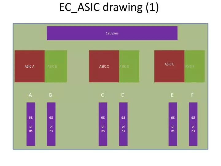
EC_ASIC drawing (1). 120 pins. ASIC A. ASIC B. ASIC C. ASIC D. ASIC E. ASIC F. A. B. C. D. E. F. 68 pins. 68 pins. 68 pins. 68 pins. 68 pins. 68 pins. EC_ASIC top view. 15 mm. Fixation holes. 80 mm. 2 0 mm. 159 mm. EC_ASIC drawing (2). TOP View. 56 mm.

E N D
EC_ASIC drawing (1) 120 pins ASIC A ASIC B ASIC C ASIC D ASIC E ASIC F A B C D E F 68 pins 68 pins 68 pins 68 pins 68 pins 68 pins
EC_ASIC top view 15 mm Fixation holes 80 mm 20 mm 159 mm
TOP View 56 mm 56 mm EC_ASIC (1.6 mm thick) 120 pins connector connector connector connector connector connector connector Mechanical structure ~ 8 mm Mechanical structure
Bottom View 56 mm 56 mm EC_ASIC (1.6 mm thick) 68 pins connectorfrom EC_ASIC (3.5 mm) + 68 pins connectorfrom EC_anode (8.5 mm) + EC_anode pcb (1.2 mm) Mechanical structure ~ 8 mm Mechanical structure
Side view –estimation ASIC CONNECTORS EC_ASIC board EC_anode Mechanical structure
VERSION USED HVPS-1 - HVPS-2 - HK - PDM-Board Interface Synoptic : 1st flight version 28V (S) BAT_RET (P) 1 GND_28V (S) 3.3V (S) 28V_BAT (P) 2 GND_3.3V (S) D-Sub 9 F D-Sub 9M D-SUB 25 F D-SUB 25 M 6 C-W 3 C-W 3 ON/OFF 3 0-2.44V 6 x 14 HV lines 3 STATUS 4 SWITCHCOMMANDS 3 x 14 HV lines HVPS-2 HVPS-1 CS_DAC CS_DAC MOSI 6 SCK 3 MOSI 0-2.44V 6 DAC 3 DAC CS_OUT SCK CS_IO 9 6 bidirectional signals ON/OFF I/O expanders MOSI MISO 9 6 status signals D-Sub 9M SCK STATUS D-Sub 9 F Interrupt 4 SWITCHCOMMANDS MOSI MISO SCK Interrupt 2 2 2 2 2 2 2 2 2 2 2 differential transmitters GND_M 4 differential receivers 4 differential receivers GND_M BATTERY 24 wires D-Sub 15 F 4 Differential signals (LVDS) ( x2 = 8 wires)between PDM_Board and HVPS-1 6 Differential signals (LVDS) ( x2 = 18 wires)between HK and HVPS-1 D-Sub 15 M Micro-D 9 M D-Sub 15 M D-Sub 15 F Micro-D 9 F HVPS-1 would have DC/DC converters to isolate the powers GND_M HK PDM_Board 4 differential transmitters 2 differential receivers 4 differential transmitters
Full PDM and potential areas for HVPS • 2 possibilities for HVPS: • 20 x 115 mm2 • 29 x 53 mm2 After discussions withJaceks, APC group and Pierre 27 x 53 mm2 chosed
Reminder of the cables/interfaces/connections 9 lines toward PDM board (9 micro-D) 28 V + gnd battery (9 D-SUB) HVPS2 HVPS1 15 lines toward HK (15 D-SUB) 14 x 3 HV cables 14 x 6 HV cables 25 lines (25 D-SUB)
3D view of the HPVS D-SUB 25 F To HVPS-2 D-SUB 15 F To HK D-SUB 9 F To Battery 159 mm 159 mm Micro-D 9 M To PDM_Board HVPS-1 53 mm D-SUB 25 M To HVPS-1 HVPS-2 53 mm 14 * 3 HV cables 27 mm 27 mm 14 * 6 HV cables NB: 159 mm and 53 mm are the maximum available Better if it is less than that to fit more easily.
Fixation with 2 plates Plate used to fixe the HVPS to the mechanical structure on the side. Top view
Lateralview ~56 mm ~56 mm ~53 mm Fixation of the HVPS To the fixation plate Fixation to the Back part of the PDM mechanical Structure. ~27 mm ZONE where to put the holes for the cables ZONE where to put the holes for the cables ~120 mm Fixation plate ~120 mm
Other possible zones for cables ~56 mm ~56 mm ZONE where to put the holes for the cables ZONE where to put the holes for the cables If HVPSs don’t lay directly on the fixation plate like bellow ~53 mm ~27 mm ZONE where to put the holes for the cables ZONE where to put the holes for the cables ~120 mm ~120 mm
Another (better) option: The plate could have half height and be fixed to the mechanical structure with 6 screws. ~56 mm ~56 mm ZONE where to put the holes for the cables ZONE where to put the holes for the cables ~53 mm ~60 mm OR ZONE where to put the holes for the cables
HVPS2 6CW + Commands +DAC HVPS1 3CW + DAC + all DC/DCs EC_anode Flex cables EC_HV boardsshouldbeorientedlikethat Ballon heater (fixation)
HVPS1 HVPS2 Positionning of the PDM board on the PDM
Positionning of the PDM board on the PDM with respect to the Balloon mechanic Ballon heater (fixation) FPGA
Positionning of the PDM board on the PDM with respect to the Balloon mechanic