Download
1 / 88
1.24k likes | 2.25k Views
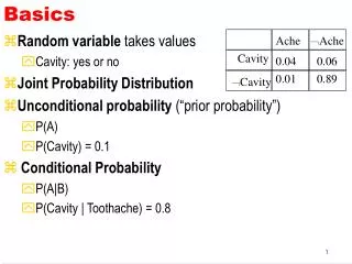
Protection Basics. Presented by John S. Levine, P.E. Levine Lectronics and Lectric, Inc. 770 565-1556 John@L-3.com. Protection Fundamentals. By John Levine. Outline. Introductions Tools Enervista Launchpad On – Line Store Demo Relays at Levine ANSI number Training CD’s

E N D
Protection Basics Presented by John S. Levine, P.E. Levine Lectronics and Lectric, Inc. 770 565-1556 John@L-3.com 1 GE Consumer & Industrial Multilin
Protection Fundamentals ByJohn Levine 2 GE Consumer & Industrial Multilin
Outline • Introductions • Tools • Enervista Launchpad • On – Line Store • Demo Relays at Levine • ANSI number • Training CD’s • Protection Fundamentals 3 GE Consumer & Industrial Multilin
Objective • We are here to help make your job easier. This is very informal and designed around Applications. Please ask question. We are not here to “preach” to you. • The knowledge base in the room varies greatly. If you have a question, there is a good chance there are 3 or 4 other people that have the same question. Please ask it. 4 GE Consumer & Industrial Multilin
Tools 5 GE Consumer & Industrial Multilin
6 GE Consumer & Industrial Multilin
Demo Relays at L-3 7 GE Consumer & Industrial Multilin
Relays at L-3 8 GE Consumer & Industrial Multilin
9 GE Consumer & Industrial Multilin
GE Multilin Training CD’s 10 GE Consumer & Industrial Multilin
ANSI Symbols 11 GE Consumer & Industrial Multilin
Conversion of Electro-Mechanical to Electronic sheet 12 GE Consumer & Industrial Multilin
PowerPoint presentations at: http://l-3.com/private/ieee/ 13 GE Consumer & Industrial Multilin
Protection Fundamentals 14 GE Consumer & Industrial Multilin
Desirable Protection Attributes • Reliability: System operate properly • Security: Don’t trip when you shouldn’t • Dependability: Trip when you should • Selectivity: Trip the minimal amount to clear the fault or abnormal operating condition • Speed: Usually the faster the better in terms of minimizing equipment damage and maintaining system integrity • Simplicity: KISS • Economics: Don’t break the bank 15 GE Consumer & Industrial Multilin
Art & Science of Protection • Selection of protective relays requires compromises: • Maximum and Reliable protection at minimum equipment cost • High Sensitivity to faults and insensitivity to maximum load currents • High-speed fault clearance with correct selectivity • Selectivity in isolating small faulty area • Ability to operate correctly under all predictable power system conditions 16 GE Consumer & Industrial Multilin
Art & Science of Protection • Cost of protective relays should be balanced against risks involved if protection is not sufficient and not enough redundancy. • Primary objectives is to have faulted zone’s primary protection operate first, but if there are protective relays failures, some form of backup protection is provided. • Backup protection is local (if local primary protection fails to clear fault) and remote (if remote protection fails to operate to clear fault) 17 GE Consumer & Industrial Multilin
Primary Equipment & Components • Transformers - to step up or step down voltage level • Breakers - to energize equipment and interrupt fault current to isolate faulted equipment • Insulators - to insulate equipment from ground and other phases • Isolators (switches) - to create a visible and permanent isolation of primary equipment for maintenance purposes and route power flow over certain buses. • Bus - to allow multiple connections (feeders) to the same source of power (transformer). 18 GE Consumer & Industrial Multilin
Primary Equipment & Components • Grounding - to operate and maintain equipment safely • Arrester - to protect primary equipment of sudden overvoltage (lightning strike). • Switchgear – integrated components to switch, protect, meter and control power flow • Reactors - to limit fault current (series) or compensate for charge current (shunt) • VT and CT - to measure primary current and voltage and supply scaled down values to P&C, metering, SCADA, etc. • Regulators - voltage, current, VAR, phase angle, etc. 19 GE Consumer & Industrial Multilin
Types of Protection Overcurrent • Uses current to determine magnitude of fault • Simple • May employ definite time or inverse time curves • May be slow • Selectivity at the cost of speed (coordination stacks) • Inexpensive • May use various polarizing voltages or ground current for directionality • Communication aided schemes make more selective 20 GE Consumer & Industrial Multilin
Instantaneous Overcurrent Protection (IOC) & Definite Time Overcurrent • Relay closest to fault operates first • Relays closer to source operate slower • Time between operating for same current is called CTI (Clearing Time Interval) Distribution Substation 21 GE Consumer & Industrial Multilin
(TOC) Coordination • Relay closest to fault operates first • Relays closer to source operate slower • Time between operating for same current is called CTI Distribution Substation 22 GE Consumer & Industrial Multilin
Time Overcurrent Protection (TOC) • Selection of the curves uses what is termed as a “ time multiplier” or “time dial” to effectively shift the curve up or down on the time axis • Operate region lies above selected curve, while no-operate region lies below it • Inverse curves can approximate fuse curve shapes 23 GE Consumer & Industrial Multilin
Time Overcurrent Protection(51, 51N, 51G) Multiples of pick-up 24 GE Consumer & Industrial Multilin
Types of Protection Differential • current in = current out • Simple • Very fast • Very defined clearing area • Expensive • Practical distance limitations • Line differential systems overcome this using digital communications 26 GE Consumer & Industrial Multilin
Differential • Note CT polarity dots • This is a through-current representation • Perfect waveforms, no saturation 27 GE Consumer & Industrial Multilin
Differential • Note CT polarity dots • This is an internal fault representation • Perfect waveforms, no saturation 28 GE Consumer & Industrial Multilin
Types of Protection Voltage • Uses voltage to infer fault or abnormal condition • May employ definite time or inverse time curves • May also be used for undervoltage load shedding • Simple • May be slow • Selectivity at the cost of speed (coordination stacks) • Inexpensive 29 GE Consumer & Industrial Multilin
Types of Protection Frequency • Uses frequency of voltage to detect power balance condition • May employ definite time or inverse time curves • Used for load shedding & machinery under/overspeed protection • Simple • May be slow • Selectivity at the cost of speed can be expensive 30 GE Consumer & Industrial Multilin
Types of Protection Power • Uses voltage and current to determine power flow magnitude and direction • Typically definite time • Complex • May be slow • Accuracy important for many applications • Can be expensive 31 GE Consumer & Industrial Multilin
Types of Protection Distance (Impedance) • Uses voltage and current to determine impedance of fault • Set on impedance [R-X] plane • Uses definite time • Impedance related to distance from relay • Complicated • Fast • Somewhat defined clearing area with reasonable accuracy • Expensive • Communication aided schemes make more selective 32 GE Consumer & Industrial Multilin
Z T B 2 Z A T 1 21 21 A B Source Impedance X Z L • Relay in Zone 1 operates first • Time between Zones is called CTI R 33 GE Consumer & Industrial Multilin
TypicalBulkPower System Generation-typically at 4-20kV Transmission-typically at 230-765kV Receives power from transmission system and transforms into subtransmission level Subtransmission-typically at 69-161kV Receives power from subtransmission system and transforms into primary feeder voltage Distribution network-typically 2.4-69kV Low voltage (service)-typically 120-600V 36 GE Consumer & Industrial Multilin
Transformer zone Bus zone Bus zone Bus zone Unit Generator-Tx zone Line zone Motor zone Transformer zone ~ XFMR Bus Motor Line Bus Bus Generator XFMR ProtectionZones • Generator or Generator-Transformer Units • Transformers • Buses • Lines (transmission and distribution) • Utilization equipment (motors, static loads, etc.) • Capacitor or reactor (when separately protected) 37 GE Consumer & Industrial Multilin
Relay Zone A Relay Zone A Zone B Zone B Zone A Zone A Relay Zone B Relay Zone B CTs are located at both sides of CB-fault between CTs is cleared from both remote sides CTs are located at one side of CB-fault between CTs is sensed by both relays, remote right side operate only. Zone Overlap • Overlap is accomplished by the locations of CTs, the key source for protective relays. • In some cases a fault might involve a CT or a circuit breaker itself, which means it can not be cleared until adjacent breakers (local or remote) are opened. 38 GE Consumer & Industrial Multilin
What Info is Required to Apply Protection • One-line diagram of the system or area involved • Impedances and connections of power equipment, system frequency, voltage level and phase sequence • Existing schemes • Operating procedures and practices affecting protection • Importance of protection required and maximum allowed clearance times • System fault studies • Maximum load and system swing limits • CTs and VTs locations, connections and ratios • Future expansion expectance • Any special considerations for application. 43 GE Consumer & Industrial Multilin
C37.2: Device Numbers • Partial listing 44 GE Consumer & Industrial Multilin
One Line Diagram • Non-dimensioned diagram showing how pieces of electrical equipment are connected • Simplification of actual system • Equipment is shown as boxes, circles and other simple graphic symbols • Symbols should follow ANSI or IEC conventions 45 GE Consumer & Industrial Multilin
1-Line Symbols [1] 46 GE Consumer & Industrial Multilin
1-Line Symbols [2] 47 GE Consumer & Industrial Multilin
1-Line Symbols [3] 48 GE Consumer & Industrial Multilin
1-Line Symbols [4] 49 GE Consumer & Industrial Multilin
1-Line [1] 50 GE Consumer & Industrial Multilin
3-Line 52 GE Consumer & Industrial Multilin
CB Trip Circuit (Simplified) 55 GE Consumer & Industrial Multilin
Lock Out Relay 58 GE Consumer & Industrial Multilin
CB Coil Circuit Monitoring:T with CB Closed; C with CB Opened 59 GE Consumer & Industrial Multilin
CB Coil Circuit Monitoring:Both T&C Regardless of CB state 60 GE Consumer & Industrial Multilin
Current Transformers • Current transformers are used to step primary system currents to values usable by relays, meters, SCADA, transducers, etc. • CT ratios are expressed as primary to secondary; 2000:5, 1200:5, 600:5, 300:5 • A 2000:5 CT has a “CTR” of 400 61 GE Consumer & Industrial Multilin