Download
1 / 105
1.05k likes | 1.07k Views
Relational Databases. Introduction. Relational model Normalization Mapping a conceptual ER model to a relational model Mapping a conceptual EER model to a relational model. Relational Model. Basic concepts Formal definitions Types of keys Relational constraints Example relational model.

E N D
Introduction • Relational model • Normalization • Mapping a conceptual ER model to a relational model • Mapping a conceptual EER model to a relational model
Relational Model • Basic concepts • Formal definitions • Types of keys • Relational constraints • Example relational model
Basic Concepts • The relational model was first formalized by Edgar F. Codd in 1970 • A Relational Model for Large Shared Data Banks, Communications of the ACM, June 1970 • The relational model is a formal data model with a sound mathematical foundation, based on set theory and first-order predicate logic • No graphical representation • Commonly adopted to build both logical and internal data models • Microsoft SQL Server, IBM DB2, and Oracle
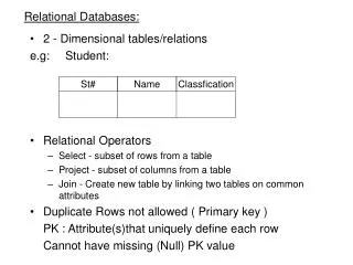
Basic Concepts • A database is represented as a collection of relations • A relation is defined as a set of tuples that each represent a similar real-world entity • The strength of the relational approach to data management comes from the formal foundation provided by the theory of relations • A tuple is an ordered list of attribute values that each describe an aspect of an entity
Basic Concepts • The schema (or description) of a relation: Denoted by R(A1, A2, .....An) R is the name of the relation The attributes of the relation are A1, A2, ..., An • Examples • Student (Studentnr, Name, HomePhone, Address) • Professor (SSN, Name, HomePhone, OfficePhone, E-mail) • Course (CourseNo, CourseName) • Each attribute has a domain or a set of valid values; for example, the domain of SSN is 9-digit numbers
Formal Definitions • A domain specifies the range of admissible values for an attribute type • e.g., gender domain, time domain • Each attribute type is defined using a corresponding domain • A domain can be used multiple times in a relation
Formal Definitions • A relation R(A1, A2, A3,… An) can now be formally defined as a set of m tuples r = {t1, t2, t3,… tm} whereby each tuple t is an ordered list of n values t = <v1, v2, v3,… vn> corresponding to a particular entity • Each value vi is an element of the corresponding domain, dom(Ai), or is a special NULLvalue • NULL value means that the value is missing, irrelevant, or not applicable
Formal Definitions • The relation state is a subset of the Cartesian product of the domains of its attributes • Each domain contains the set of all possible values the attribute can take • Formally, • Given R(A1, A2, .........., An) • r(R) dom (A1) X dom (A2) X ....X dom(An) • R(A1, A2, …, An) is the schema of the relation • R is the name of the relation • A1, A2, …, An are the attributes of the relation
Formal Definitions - Example • Let R(A1, A2) be a relation schema: • Let dom(A1) = {0,1} • Let dom(A2) = {a,b,c} • Then: dom(A1) X dom(A2) is all possible combinations: {<0,a> , <0,b> , <0,c>, <1,a>, <1,b>, <1,c> } • The relation state r(R) dom(A1) X dom(A2) • For example: r(R) could be {<0,a> , <0,b> , <1,c> } • this is one possible state (or “population” or “extension”) r of the relation R, defined over A1 and A2. • It has three 2-tuples: <0,a> , <0,b> , <1,c>
Formal Definitions • A relation essentially represents a set (no ordering + no duplicates!) • The domain constraint states that the value of each attribute type A must be an atomic and single value from the domain dom(A) • Example: COURSE(coursenr, coursename, study points) (10, Principles of Database Management, 6) (10, {Principles of Database Management, Database Modeling}, 6) WRONG!
Formal Definitions • A relation R of degree n on the domains dom(A1), dom(A2), dom(A3), … , dom(An) can also be alternatively defined as a subset of the Cartesian product of the domains that define each of the attribute types
Types of Keys • Superkeys and keys • Candidate keys, primary keys, alternative keys • Foreign keys
Superkeys and Keys • A superkey is defined as a subset of attribute types of a relation R with the property that no two tuples in any relation state should have the same combination of values for these attribute types • A superkey specifies a uniqueness constraint • A superkey can have redundant attribute types • Example: (Studentnr, Name, HomePhone)
Superkeys and Keys • A key K of a relation scheme R is a superkey of R with the additional property that removing any attribute type from K leaves a set of attribute types that is no superkey of R • A key does not have any redundant attribute types (minimal superkey) • Example: Studentnr • The key constraint states that every relation must have at least one key that allows uniquely identifying its tuples
Candidate Keys, Primary Keys, and Alternative Keys • A relation may have more than one key (candidate keys) • PRODUCT: product number and product name • The primary key is used to identify tuples in the relation, to establish connections to other relations, and for storage purposes • Entity integrity constraint: attribute types that make up the primary key should always satisfy a NOT NULL constraint • Other candidate keys are then referred to as alternative keys
Foreign Keys • A set of attribute types FK in a relation R1 is a foreign key of R1 if two conditions are satisfied (referential integrity constraint) • The attribute types in FK have the same domains as the primary key attribute types PK of a relation R2 • A value FK in a tuple t1 of the current state r1 either occurs as a value of PK for some tuple t2 in the current state r2 or is NULL
Example Relational Data Model SUPPLIER(SUPNR, SUPNAME, SUPADDRESS, SUPCITY, SUPSTATUS) PRODUCT(PRODNR, PRODNAME, PRODTYPE, AVAILABLE QUANTITY) SUPPLIES(SUPNR, PRODNR, PURCHASE_PRICE, DELIV_PERIOD) PURCHASE_ORDER(PONR, PODATE, SUPNR) PO_LINE(PONR, PRODNR, QUANTITY)
Normalization • Overview • Insertion, deletion, and update anomalies • Informal normalization guidelines • Functional dependencies and prime attribute type • Normalization forms
Overview • Normalization of a relational model is a step-by-step process of analyzing the given relations to ensure that they do not contain any redundant data • The goal of normalization is to ensure that no anomalies can occur during data insertion, deletion, or update
Database Design Guidelines • Guideline 1: Each tuple in a relation should represent one entity (or relationship instance); results in a clear semantics • Guideline 2: Design a schema that does not suffer from the insertion, deletion and update anomalies • Guideline 3: Relations should be designed such that their tuples will have as few NULL values as possible • Guideline 4: The relations should be designed to satisfy the lossless join condition
Guidelines 1: Clear Semantics • GUIDELINE 1: Informally, each tuple in a relation should represent one entity or relationship instance • Attributes of different entities (EMPLOYEEs, DEPARTMENTs, PROJECTs) should not be mixed in the same relation • Only foreign keys should be used to refer to other entities • Entity and relationship attributes should be kept apart as much as possible. • Bottom Line:Design a schema that can be explained easily relation by relation. The semantics of attributes should be easy to interpret.
A simplified COMPANY relational database schema Figure 14.1 A simplified COMPANY relational database schema.
Guidelines 2: Remove or Minimize Anomalies • Design a schema that does not suffer from the insertion, deletion and update anomalies. • If there are any anomalies present, then note them so that applications can be made to take them into account.
Example of Update Anomaly • Consider the relation: • EMP_PROJ(Emp#, Proj#, Ename, Pname, No_hours) • Update anomaly: • Changing the name of project number P1 from “Billing” to “Customer-Accounting” may cause this update to be made for all employees working on project P1
Example of Insertion Anomaly • Consider the relation: • EMP_PROJ(Emp#, Proj#, Ename, Pname, No_hours) • Insert anomaly: • Cannot insert a project unless an employee is assigned to it • Conversely • Cannot insert an employee unless an he/she is assigned to a project
Example of Deletion Anomaly • Consider the relation: • EMP_PROJ(Emp#, Proj#, Ename, Pname, No_hours) • Delete anomaly: • When a project is deleted, it will result in deleting all the employees who work on that project. • Alternately, if an employee is the sole employee on a project, deleting that employee would result in deleting the corresponding project.
Guideline 3: Minimize Null Values • Relations should be designed such that their tuples will have as few NULL values as possible • Attributes that are NULL frequently could be placed in separate relations (with the primary key) • (Confusing) Reasons for nulls: • Attribute not applicable or invalid • Attribute value unknown (may exist) • Value known to exist, but unavailable
Guideline 4: Lossless Join • Bad designs for a relational database may result in erroneous results for certain JOIN operations • The "lossless join" property is used to guarantee meaningful results for join operations • The relations should be designed to satisfy the lossless join condition • No spurious tuples should be generated by doing a natural-join of any relations
Fundamental Concepts for Better Design • The functional dependencies (FDs) and the normalization process
Functional Dependencies and Prime Attribute Type • A functional dependency X Y between two sets of attribute types X and Y implies that a value of X uniquely determines a value of Y • There is a functional dependency from X to Y or Y is functionally dependent on X • Examples: • SSN ENAME • PNUMBER {PNAME, PLOCATION} • {SSN, PNUMBER} HOURS
Functional Dependencies and Prime Attribute Type • A prime attribute type is an attribute type that is part of a candidate key • Example: R1(SSN, PNUMBER, PNAME, HOURS) • Prime attribute types: SSN and PNUMBER • Non-prime attribute types: PNAME and HOURS
Normalization Forms • First normal form (1 NF) • Second normal form (2 NF) • Third normal form (3 NF) • Boyce–Codd normal form (BCNF) • Fourth normal form (4 NF)
First Normal Form (1 NF) • The first normal form (1 NF) states that every attribute type of a relation must be atomic and single-valued • No composite or multi-valued attribute types (domain constraint!) • SUPPLIER(SUPNR, NAME(FIRST NAME, LAST NAME), SUPSTATUS) • SUPPLIER(SUPNR, FIRST NAME, LAST NAME, SUPSTATUS)
First Normal Form (1 NF) • DEPARTMENT(DNUMBER, DLOCATION, DMGRSSN) • Assumption: a department can have multiple locations and multiple departments are possible at a given location • DEPARTMENT(DNUMBER, DMGRSSN) • DEP-LOCATION(DNUMBER, DLOCATION)
First Normal Form (1 NF) • R1(SSN, ENAME, DNUMBER, DNAME, PROJECT(PNUMBER, PNAME, HOURS)) • Assume an employee can work on multiple projects and multiple employees can work on the same project • R11(SSN, ENAME, DNUMBER, DNAME) • R12(SSN, PNUMBER, PNAME, HOURS)
Second Normal Form (2 NF) • A functional dependency X Y is a full functional dependency if removal of any attribute type A from X means that the dependency does not hold anymore • Examples: SSN, PNUMBER HOURS; PNUMBER PNAME • A functional dependency X Y is a partial dependency if an attribute type A from X can be removed from X and the dependency still holds • Example: SSN, PNUMBER PNAME
Second Normal Form (2NF) • A relation R is in the second normal form (2NF) if it satisfies 1NF and every non-prime attribute type A in R is fully functional dependent on any key of R • If the relation is not in second normal form, we must: • Decompose it and set up a new relation for each partial key together with its dependent attribute types • Keep a relation with the original primary key and any attribute types that are fully functional dependent on it
Second Normal Form (2 NF) • R1(SSN, PNUMBER, PNAME, HOURS) • Assume an employee can work on multiple projects; multiple employees can work on the same project; and a project has a unique name • R11(SSN,PNUMBER, HOURS) • R12(PNUMBER, PNAME)