Download
1 / 33
330 likes | 428 Views
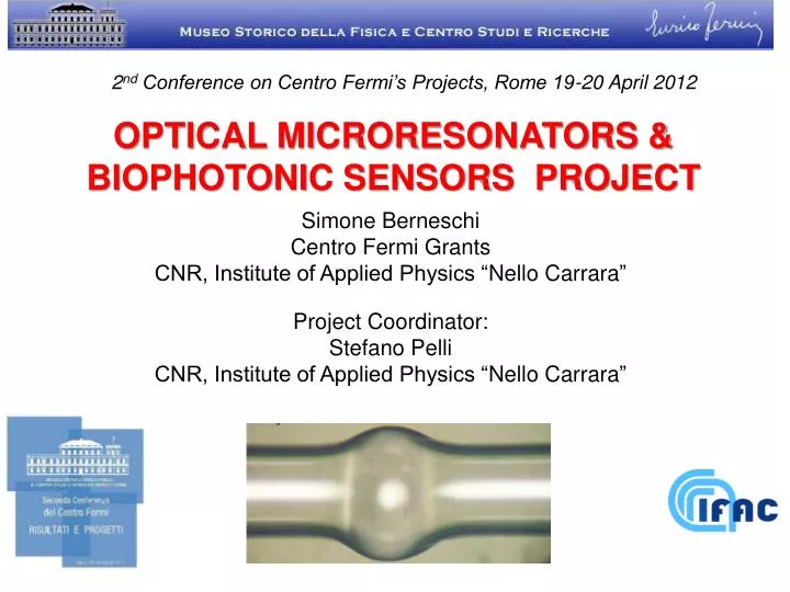
2 nd Conference on Centro Fermi’s Projects, Rome 19-20 April 2012. OPTICAL MICRORESONATORS & BIOPHOTONIC SENSORS PROJECT. Simone Berneschi Centro Fermi Grants CNR, Institute of Applied Physics “ Nello Carrara ”. Project Coordinator: Stefano Pelli

E N D
2nd Conference on Centro Fermi’s Projects, Rome 19-20 April 2012 OPTICAL MICRORESONATORS & BIOPHOTONIC SENSORS PROJECT Simone Berneschi Centro Fermi Grants CNR, Institute of Applied Physics “NelloCarrara” Project Coordinator: Stefano Pelli CNR, Institute of Applied Physics “NelloCarrara”
OUTLINE • Motivations; • Objectives; • WGM microresonators: a brief overview; • Applications & Results; • NL effects; • biosensors; • Conclusions
MOTIVATIONS « …smallerobjects in nature are not just scaledreplicas of similar big objects and in facttheyhaveimprovedproperties…» Galileo «DialogueConcerningTwo New Sciences» (1638) • Light – matterinteractionincreases in the presence of small objects; • High Q microcavities, with strong spatiallocalization of the field, wellrespond to thisprinciple and receive an evengreaterinterest in manyfundamentalprocesses in photonics (e.g.: QED & NL processes; biosensing….)
OBJECTIVES InvestigatingWhispering Gallery Modes (WGMs) microcavities for: • Developinghighly sensitive, label free biosensors (earlydiagnosis); (microsphere/microbubble) • Developingall-opticalswitch by means of NL polymericcoating; (microsphere) • Studingpossibleintegrationsolutions with optical planar devices. (millidisk)
WGMs RESONATORS • The WhisperingGallery phenomenon was initially described by Lord Rayleigh based on observations in St. Paul’s Cathedral in London; • a whisper spoken close to the wall can be heard all the way along the gallery, 42 m to the other side, thus the term “whispering gallery” Lord Rayleigh (1842 – 1919) Whispering Gallery under the cupola of the St. Paul’sCathedral in London L. Rayleigh, “The Problem of the Whispering Gallery,” Philosophical Magazine 20, 1001–1004 (1910).
Microdisks Field radial component for the fundamental mode Evanescent field tail Field polar component for the fundamental mode (spherical Legendre function) Field azimuthal component (periodical function) WGMs RESONATORS • Microbubble • Microspheres • light canberesonantlyguidedby total internalreflection, along an equatorial plane, with long cavity lifetime and strong spatial confinement; Maxwell + boundaryconditions:
Prism Tapered fiber Surface waveguide Hybrid fiber-prism WGMs RESONATORS Efficientand robust couplingofthe light tothecavityrequires: phase matching and mode overlap! • Approaches for efficient evanescent coupling of light into the microspheres:
camera Vis. LD Monitor camera Detector piezo Tunable LD Mux dn=300 KHz Dn=1.5 GHz Modulator Scope dn WGMs RESONATORS Q factormeasurement: experimental setup • From WGM spectral linewidthdν • Q=ν/dν
electrodes FiberTip WGMs RESONATORS SiO2microspheres by fusion splicing • A cleavedtip of the fiberisinsertedbetweentwo metal electrodes; • Arcdischargespartiallymelts the fibertip; • Surfacetensionforces produce the sphericalshape. D = 2R = 150 – 350μm depending on the number of shots
WGMs RESONATORS Crystallinemicrodisk by polishing • Partialmelting + surfacetensioneffectcannot be applied to crystals. • Polishing procedure by using a home-made lapping station. The almost spherical profile of the edges is obtained through a rotational stage whose pivot point can be finely adjusted. • Polishing protocol: • Grinding phase steps • (abrasive disk); • Fine polishing phase • (diamond suspensions);
WGMs RESONATORS CRYSTALLINE MICRODISK INTEGRATION Q = 1.3 108 The system is all in guided integrated optics architecture (LiNbO3) ! G.Nunzi Conti et al., Opt. Express, 19, 3651 (2011)
NL EFFECTS IN COATED MICROSPHERES PUMP-PROBE Configuration: pump All-opticalswitching for a probe signalIprobe by a resonantpumpbeamIpumpwhichchange the coatingrefractiveindex and hence the resonance position. probe Motivation: optical switch based on electronic Kerr effect (n = n0 + n2 I) on spherical WGMR coated by a nonlinear medium; Large resonance shift obtained on low time scales (10-12 s) using intensities well below the damage thresholds of the polymers.
NL EFFECTS IN COATED MICROSPHERES Coatedmicrospheres Wetlayer formation Solvent evaporation Dipping Polymer: liquid crystal polyfluorene (λpeak = 379 nm; n2 Re ((3)) = 2 10-10 cm2/W; β Im ((3))= = 2 10-7 cm/W) Solution: 0.1 mg/ml of polymer in toluene
NL EFFECTS IN COATED MICROSPHERES Q factor from spectrallinewidth Uncoatedmicrosphere Coatedmicrosphere Q = 1.5 108 Q = 5 106 (@ 1550 nm) Coatingthickness< 100 nm
NL EFFECTS IN COATED MICROSPHERES An optically induced shift of WGM of up to 250 MHz is obtained in the CW pump regime, which is nearly an order of magnitude smaller as compared to the pulsed probe regime. Such a difference of the values of the shift induced optically by the power of the pump radiation is an indicator of the nonlinear-optical mechanism of the shift. S. Soria et al. Opt. Express (2011)
Wavelength Sweep Generator DFB Laser Power Detector SiO2 MICROSPHERES AS OPTICAL BIOSENSORS WGMsare morphologicaldependent: anychange in itssurroundingenvironment (i.e. refractiveindex) or on itssurface (due to some chemical and/or biochemicalbonding) causes a shift of the resonances and reduces the Q factorvalue. By measuringthisshift, itispossibleto obtainthe refractiveindexchange and/or the concentration of the analyte. R ’ R • from the resonancecondition:
SiO2 MICROSPHERES FOR PROTEIN APTASENSORS Aptamers: are RNA or DNA molecules (ca. 30 to 100 nucleotides) that recognize specific ligands and that are selected in vitro from vast populations of random sequences[so named in 1990 by Ellington and Szostak]. • They exhibit: • comparabile affinity and specificity • more reproducibility and higher stability • reversible denaturationandease of modification
100 m SiO2 MICROSPHERES FOR PROTEIN APTASENSORS Functionalization procedure Activation Silanization Thrombin Binding Aptamer (TBA) immobilization Passivation (mercapto-ethanol 1mM 1h) OH OH OH OH OH OH OH OH OH OH OH OH OH OH OH OH OH Dithiol-TBA 5'-GGTTGGTGTGGTTGG- 3' 10M in carbonate buffer 0.5M pH9 for 2 hours at 60 rpm c) Mercaptopropyl- trimethoxysilane 1% v/v toluene for 10 minutes at 60°C b) Piranha treatment: H2SO4: H2O2 4 : 1 for 3 minutes a)
SiO2 MICROSPHERES FOR PROTEIN APTASENSORS Q factor measurement (@ 773 nm) bare microsphere Q = 4.0 107 silanizedmicrosphere Q = 4.0 106 (in aqueousenvironment) Thrombinbindingmicrosphere Uniformdistribution of the film Coatingthickness< 100 nm Q = 8.0 105 (in buffer solution) L. Pasquardini et al. , J. of Biophotonics (2012)
SiO2 MICROSPHERES FOR PROTEIN APTASENSORS Set – Up measurement DetectedProteins: Thrombin: coagulationfactor Itinvolvesmanypathological diseaseslike: Aatherosclerosis; marker for some cancer; VEGF (VascularEndothelial GrowthFactor): regolator for angiogenesis;
SiO2 MICROSPHERES FOR PROTEIN APTASENSORS Binding measurements showed that derivatized glass microspheres can act as efficient aptasensors in complex matrices: buffer and no filtered human serum. VEGF165 concentration of 0,3mg/ml in buffer Measureconditions: Thrombinconcentration of 0,3mg/ml in non filtered10% diluted human serum L. Pasquardini et al. , J. of Biophotonics (2012)
FROM MICROSPHERES TO MICROBUBBLES (MB) The opticalmicrocavity (microsphere) & couplingsystem (taperfiber) are immersed in a liquid medium (fluidiccell) Systems based on Bulk Microresonators Problems:possibleinstability on the resonance position due to the inducedperturbations by the liquidenvironment on the couplingsystem. No integratedsolution. Modulator Laser The fluidicsisintegrated inside the device (microbubble) & couplingsystem (taperedfiber) isexternalto the fluidics Systems based on Hollow Microresonators Modulator Advantage: Possibility to test liquid or gas flows insidethe microbubble without disturb the microfiber alignment. Integrated solution. Laser
WHAT IS AN OPTICAL MB: THE BASIC IDEA Antoine De Saint-Exupéry Le Petit Prince (“The Little Prince”) - 1945 M. Sumetsky et al., Opt. Lett. 35, p. 898 (2010) Similarly to the snake which has swallowed an elephant, an optical microbubble is a resonant microcavity structure, obtained starting from a microcapillary preform (the snake in the corresponding picture) by means of a particular fabrication process which locally increases the radial dimension of the hollow microtube (the elephant) along the axial direction.
OPTICAL MB FABRICATION: A NEW PROCEDURE Modified Fusion Splicer The electrodes were moved outside the splicer and placed in a U shaped holderable to rotate by 360° by means of a step by step motor. A pair of electrical wires connects the electrodes to the splicer Uniform heating of the pressurized capillary is obtained by rotation of the U shaped holder around the capillary.
OPTICAL MICROBUBBLE RESONATORS Q factor measurement Contact - Critical couplingcondition No Contact – undercouplingcondition Postnova Microbubble S. Berneschi et al., Opt. Lett. (2011)
OPTICAL MICROBUBBLE: REFRACTOMETRIC TEST A peristalticpumpisconnected to the microbubble Router = 190 μm w = 4 μm Sensibility: 0.5 nm/RIU Postnova Microbubble Different water – ethanol solutions: (4:1, 4:2, 4:3) in volume Detection Limit: 10 -6 RIU S. Berneschi et al., Opt. Lett. (2011)
CONCLUSIONS & PERSPECTIVES • Possibility to obtain high Q WGM resonators in differentmaterials and with differentfabricationprocess; • Possibility to integrate opticalWGMRs in planar structures (LiNbO3millidisk) add-dropfilters & optoelectronicsoscillators in RF systems; • Demonstrationof all – opticalswitchby NL coatedmicrospheresadd-dropconfiguration; • Demonstration of opticalmicrosphereaptasensors for protein • detection (in human serum) take the detection to the limit; • Demonstrationof opticalmicrobubbleresonatorspossibility to use thisstructures for biosensing;
RELATED PROJECTS & COLLABORATIONS AramosProject EDA OptoelectronicsOscillators CNRS, LAAS & Univ. de Toulouse, France Naomi National Project Biosensors (proteinessays) FBK (Fondazione Bruno Kessler), Trento; Ospedale di Careggi (Firenze). Collaboration with differenteuropeanResearchInstitutes & Universities (Moscow, Budapest, Trento,..) Short termmobility programCNR