Download
1 / 59
600 likes | 901 Views
課程名稱 : 積體電路分析與模擬 (Analysis and Simulation of Integrated Circuits). Text Books 1. 電腦輔助電子電路設計 , 鄭群星 , 全華 2. Reference Books 1. OrCAD PSpice and Circuit Analysis, J. Keown 2. Real Word FPGA Design with Verilog, Coffman. 任課教師及相關資料. 授課教師 : 李宗演 研究室 : 綜科館 207-4 E-mail: tylee@ntut.edu.tw

E N D
課程名稱: 積體電路分析與模擬(Analysis and Simulation of Integrated Circuits) • Text Books 1. 電腦輔助電子電路設計, 鄭群星,全華 2. • Reference Books 1. OrCAD PSpice and Circuit Analysis, J. Keown 2. Real Word FPGA Design with Verilog, Coffman
任課教師及相關資料 • 授課教師: 李宗演 • 研究室: 綜科館 207-4 • E-mail: tylee@ntut.edu.tw • URL: www.ntut.edu.tw/~tylee/ • Tel: 02-2771-2171 ext. 2251 • Office Hour: 星期三及四 10:00~12:00
Goal • Introduce the methodologies of analysis and simulation on integrated circuits • Learn the analysis and simulation techniques on analog circuits using OrCAD PSpice tool • Learn the design and simulation techniques on digital circuits using Xilinx FPGA design tool kit
Progress of Course • Analysis and Simulation Techniques on Analog Circuits Using OrCAD PSpice Tool/ 8 Weeks • Design and Simulation Techniques on Digital Circuits Using Xilinx FPGA Design Tool Kit / 8 Weeks
Scores • Term Exam 30% • Final Exam 30% • Home Works, Computer Exercises, and Others 40%
Question & Answer • ? ? ? ? ? ?
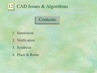
Design Concept Verification • The design is described in equations or behavioral expressions • This high-level design description is then simulated or verified to match with expected result
Design Implementation Verification • Simulates the physical design • The simulated result should match with the expected specification
Design Performance Verification • Predicts or verifies the design “quality” • Post-layout simulation with extracted RCs is needed in nanometer technology
Verification Methodologies • Dynamic simulation • Examples: SPICE, Verilog • Static verification or analysis • Examples: Formal verification, static timing analysis
Dynamic vs Static Verification • Dynamic simulation mimics the physical behavior • Difficult to select the input stimulus pattern to cover all possible verifications using dynamic simulation • More time consuming to simulate many possible test patterns • Static verification tends to validate the design still works under all possible working conditions • Static verification is less accurate and may give wrong results occasionally • Static verification is limited to digital circuits only
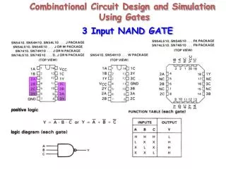
Important Simulation Technologies • Complier code logic simulation • Transistor-level SPICE-like circuit simulation • Switch-level transistor circuit simulation • Fast SPICE circuit simulation • Analog behavioral simulation • Hierarchical circuit simulation
Complied Code Logic Simulation • Complier the digital circuit into a sequence of computer machine code • Traditional interpretation method looks up the logic gate model to simulate the digital state changes • Machine code execution runs faster than procedural interpretation
SPICE Circuit Simulation • Developed at UC Berkeley in early 1970s • Models and simulations the electrical-level circuit behavior accurately • Widely used due to open release to public users • Solves the whole circuit as a single entity • Slow and limited to speed circuit size less than 100,000 elements • Earlier attempts to speed up simulation, including waveform relaxation and iterative method, failed to commercialize • Fast SPICE simulation technology achieved commercial success until late 1990s
History of Dynamic Simulation • Logic simulation and circuit simulation are converging into a mixed-signal simulation
Switch-Level Simulation • Models MOSFET as a switch • Able to model the bi-directional signal flow behavior of MOSFET • Simulates the flat transistor netlist extracted from physical layout • Simulation speed is 1,000X faster than SPICE and is close to gate-level logic simulation • Limited in digital circuit only • A hot technology in 1980s but only achieved limited commercial success
Switch-Level Timing Simulation • Models the conducting MOSFET by an equivalent resistance • Calculates the switching delay by the RC time constant • Limited to digital CMOS circuit simulation • Unable to simulate analog behavior even in digital circuits
Analog Event-Driven Simulation • Similar to digital logic simulation except the event is triggered by analog voltage change instead of logic state transition
Fast SPICE Circuit Simulation • Partitions the whole circuit into smaller subcircuits and solves each one individually • Runs 10-100X faster than SPICE • Can simulate circuits up to 5 million elements • Simulates analog behavior in digital circuits • Less accurate especially when simulating high-sensitivity analog circuits • Gets more acceptance due to new enhancements in simulating analog circuits
Analog Behavioral Simulation • Needed in top-down analog/mixed-signal design flow • Further speeds up verification • A new trend: device model described in Verilog-A • Verifies design concept instead of design implementation • Very difficult to create and characterize the analog behavior model
Use SPICE or Mixed-Signal Simulation • Mixed-signal simulator is difficult to use • No need if SPICE performance is reasonable • Fast SPICE may do a better job if majority portions are analog
Reference • A.-C. Deng, Signal Integrity in SOC Design, SOC/IP 菁英人才養成課程, 三C整合策劃推行小組, July 2002.
SPICE 模擬電路程式之功能 • DC Analysis • Small Signal Transfer Function • DC Transfer Curves • Small Signal Sensitivities • Small Signal Frequency Domain Response • Noise Analysis • Distortion Analysis • Transient Analysis • Fourier Analysis • Temperature Analysis
OrCAD PSpice使用電路描述模擬的方式(1) • 開始→程式集→OrCAD family release 9.2 Lite Edition →PSpiceAD Lite Edition • File→New→Text File • 依OrCAD PSpice描述格式將電路輸入, filename為XXX.CIR
OrCAD PSpice使用電路描述模擬的方式(4) • File→Open→XXX.CIR • Simulation File→Run XXX • View→Outputfile (出現輸出檔視窗XXX.out)
OrCAD PSpice使用電路描述模擬的方式(7) • File→Exit (Exit OrCAD PSpice)
OrCAD PSpice使用繪圖描述模擬的方式(1) • 開始→程式集→OrCAD family release 9.2.1 Lite Edition →Capture Lite Edition
OrCAD PSpice使用繪圖描述模擬的方式(2) • File→New→Project
OrCAD PSpice使用繪圖描述模擬的方式(3) • Location → 輸入C:\OrCAD pspice\project\example1 →OK (目錄要先存在) • Create a blank project
OrCAD PSpice使用繪圖描述模擬的方式(4) • Project Manager and Schematic page Editor
OrCAD PSpice使用繪圖描述模擬的方式(5) • 繪圖及模擬: 1. 取元件 ~ 直流電源 • Place → Part → Begin Search → VDC→ VDC/source.olb
OrCAD PSpice使用繪圖描述模擬的方式(6) • 繪圖及模擬: 1. 取元件 ~ 電阻 • Place → Part → Begin Search → R/analog.olb →ok (Ctrl + R 轉動用)
OrCAD PSpice使用繪圖描述模擬的方式(7) • 繪圖及模擬: 1. 取元件 ~ 地線 • Place → Ground, libraries →SOURCE, Symbol →0 →ok
OrCAD PSpice使用繪圖描述模擬的方式(8) • 繪圖及模擬: 2. 開始連線 • Place → Wire
OrCAD PSpice使用繪圖描述模擬的方式(9) • 繪圖及模擬: 3.改變元件的屬性~電源 • 在該VDC元件以mouse左鍵連續按兩次