Download
1 / 17
180 likes | 323 Views
Team “Canard” September 28th, 2006. Structures 1 QDR. 9.3 deg. 0.89ft. S wing = 4.16 ft 2. 0.3. balsa. Easy to built Good surface. Expanded polystyrene. Wing Sizing. Aerodynamics gives the geometry Load case : Resist to 10g (640ft radius at 100mph) Materials. MH 43. 0.4 ft.

E N D
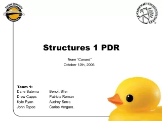
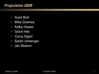
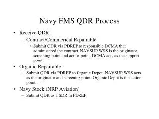
Team “Canard” September 28th, 2006 Structures 1 QDR
9.3 deg 0.89ft Swing = 4.16 ft2 0.3 balsa Easy to built Good surface Expanded polystyrene Wing Sizing • Aerodynamics gives the geometry • Load case: Resist to 10g (640ft radius at 100mph) • Materials MH 43 0.4 ft Thickness:8.5% Wing should support 50 lb With a weight of 5 lb AAE 451 Team 1
Quarter chord MAC: application of the lift Sizing Method • Discretization of the wing • Determination of the loads 1 2 3 4 • For each part, we can figure out: • The bending moment due to the lift • The torsion torque due to the aerodynamic moment AAE 451 Team 1
Distribution of Lift The lift is assumed to be linear: Lift = Wloading x Surface AAE 451 Team 1
Bending Moment L1 L2 M=L1.d1 + L2.d2 + ….. d1 MAC d2 AAE 451 Team 1
b a Minimal thickness • Assumptions: • Only bending loading • Foam doesn’t carry the load • The balsa should resist the load • We assume the shape of the airfoil is an ellipse t is figured out from IG polar inertia AAE 451 Team 1
Skin Thickness Easy to built, but 70% heavier than discretized thickness 1.53 in Optimal thickness distribution AAE 451 Team 1
Twist and Deflection • Twist • Assumption: Only the aerodynamic twist (twist due to the swept angle is neglected) • Deflection =100 mph y y’ Lift at MAC y’ with Thales theorem AAE 451 Team 1
Twist max. twist: 0.7° AAE 451 Team 1
Deflection 0.21 in AAE 451 Team 1
Carbon Spar Advantages The minimum skin thickness is too thick to bend around the airfoil shape (from experience) Method: Assume iso-rigidity for the carbon tube and the skin (EI)skin=(EI)spar 50% of the load in the spar 50% of the load in the skin Redo the calculations for the skin with 50% of load AAE 451 Team 1
Skin Thickness With Spar From this point, the structure resist without spar Cut spar at 1.50ft AAE 451 Team 1
Skin Thickness Balsa sheet thickness t = 0.06 in ($22 for 253”x36”x1/16”) 4.8 in ID ≈ 0.32 in OD ≈ 0.45 in Thickness ≈ 0.13 in Final size will depend on market availability AAE 451 Team 1
CG Estimation/Spar Location Mean Aero. Chord (MAC) Spar Length = 3.0 ft (≈1/2 of wingspan) CG Location: 33% of Mean Aerodynamic Chord AAE 451 Team 1
Tip Over Analysis y d2 z d3 d1 Ftip Wwing FLanding Gear Waircraft-Wwing -(Waircraft-Wwing) + FLG – Wwing – Ftip = 0 ∑MLG = 0 = -(Waircraft)d1 + (FLG)d3 – (Ftip)d2 Ftip ≈ 0.5 lb AAE 451 Team 1
Landing Gear Calcs Racer wheels carbon or aluminum strut depending on cost AAE 451 Team 1
Questions AAE 451 Team 1


![Data Structures [1]](https://cdn3.slideserve.com/6547756/data-structures-1-dt.jpg)