Download
1 / 66
660 likes | 831 Views
ORION AEROSPACE. Final Design review December 5, 2000. Patrick Dempsey Bridget Fitzpatrick Heather Garber Keith Hout Jong Soo Mok. ORION AEROSPACE. Presentation Overview. -Mission & Performance -Reasons for Design -3-view & aircraft dimensions -Aerodynamics -Stability and Control

E N D
ORION AEROSPACE Final Design review December 5, 2000 Patrick Dempsey Bridget Fitzpatrick Heather Garber Keith Hout Jong Soo Mok
ORION AEROSPACE Presentation Overview -Mission & Performance -Reasons for Design -3-view & aircraft dimensions -Aerodynamics -Stability and Control -Structures -Propulsion -Cost Analysis -Construction -Conclusion
ORION AEROSPACE Mission -Design and Build a R/C Airplane that must -Carry a gyro for augmenting aircraft stability -Carry a 1lb slug simulating data logging equipment -Fly inside Mollenkopf Athletic Facility -Flight duration of at least 12 minutes
M&P ORION AEROSPACE Mission & Performance Cruise & Turn Descent Climb Takeoff Land -Estimated Values -Takeoff distance: 35.5 ft -Climb angle: 12 -Cruise & Turn: 13 min -Cruise speed: 25 ft/s -Turn Radius: 20 ft -Constraint Values -MAX. Takeoff distance: 120 ft -MIN. Climb angle: 5.5 -MIN. Cruise & Turn: 12 min -MAX. Cruise speed: 30 ft/s -MIN. Turn Radius: 37.5 ft
Constraint Diagram ORION AEROSPACE • Text
Biplane Pros: Cons: ORION AEROSPACE Concept Description Biplane Configuration • Square fuselage • Rectangular wings • Conventional swept tail • Taildragger landing gear Pros: Cons: ---------------------------------------------------------------------------------------------------- Shorter Wing Span Wing Interference Increase Turn Clearance Accessibility of Equipment Increase Roll Rate Maneuverability Transporting Less Need For High Lift Devices Decalage Provides Natural Stall Recovery Less Need For High Lift Devices Induced Drag Decalage Provides Natural Stall Recovery Accessibility of Equipment
ORION AEROSPACE 3 View of SID5 -DIMENSIONS IN FEET
ORION AEROSPACE Aircraft Dimensions
ORION AEROSPACE Aerodynamics • Selection of Airfoil for Wing • Selection of Horizontal and Vertical Tail • Lift Curve • Drag Polar • -Lift to Drag Ratio vs Angle of Attack • CMARC Analysis
ORION AEROSPACE Aerodynamics
ORION AEROSPACE Aerodynamics • Airfoil Selection: Selig-Donavan 7062 • Low Reynolds Number, Slow Speed Flight • Experimental Data/ Xfoil Analysis • CL vs Alpha Curve, Drag Polar • Ease of Construction • Horizontal and Vertical Tail: Flat Plate Assumption
ORION AEROSPACE Aerodynamics
ORION AEROSPACE Aerodynamics
ORION AEROSPACE CMARC Analysis
ORION AEROSPACE Stability and Control • Feedback Loop Description • Gain Selection and Description • Static Margin, CG, and Aerodynamic Center • Control Surface and Tail Sizing • Horizontal and Vertical Tail Size Verification • Trim Diagram • Pertinent Static Stability Derivatives and Comparison
ORION AEROSPACE TX Pilot Aircraft + Servo RX +/ - ? Pitch Rate Gyro Loop Closure Description • Rate feedback in the pitch axis • Vary the stability of the short period mode • Block Diagram Pilot inputs elevator command Servo converts voltage to elevator deflection Sign of feedback gain is chosen to stabilize or destabilize the mode
Feedback Gain Implementation • Completed flight in Mollenkopf w/ stabilizing gain • Behaved as expected,pilot described response as sluggish • Damped out oscillations when perturbed Stabilizing Case Destabilizing Case
ORION AEROSPACE Static Margin, CG, and Aerodynamic Center • Static Margin Desired is 10%, puts CG at the 27% chord location • Past 451 final reports agree that 10-15% is an agreeable range for model aircraft • Pick toward lower end of range to help with trimming • Pick desired Static Margin and place internal equipment to obtain the CG that gives this Static Margin XLE XCG XNP XACHT Distances in ft
ORION AEROSPACE Sizing of Control Surfaces And Tails • Historical Methods (as described in Raymer’s Aircraft Design: A Conceptual Approach) • Control Surfaces • Guidelines • Ailerons: 15-25% chord and 50–90% span • Elevators: 25–50% chord and ~90% span • Rudders: 25–50% chord and ~90% span • Selected: • Ailerons: 15% chord and 90% span • Elevators: 40% chord and 95% span • Rudder: 40% chord and full span • Tails • Sized using the Tail Volume coefficient method • Horizontal Tail Volume Coefficient = 0.45 • Vertical Tail Volume Coefficient = 0.04 • Coefficients based on old 451 Air designs
ORION AEROSPACE 4 3.5 3 2.5 2 1.5 1 0.5 2.5 2.75 3 3.25 3.5 3.75 4 4.25 4.5 4.75 5 Analysis Of Tails • Horizontal Tail Longitudinal X-Plot L r e q Lmax p o s s Design Point (3.3 ft^2) X c g X n p Distance / Wing Chord 2 Horizontal Tail Area [ft ]
ORION AEROSPACE Analysis Of Tails • Vertical Tail • “Weathercock” Stability Criterion (Dr. Roskam’s Airplane Design Series) Lateral X-Plot 0.25 0.2 Design Point (1.3 ft^2) 1] 0.15 - [rad a t e Constraint Point b Cn 0.1 0.05 0 0.5 0.75 1 1.25 1.5 1.75 2 2.25 2.5 2 Vertical Tail Area [ft ]
ORION AEROSPACE Trim Diagram • Text
ORION AEROSPACE Trim Diagram
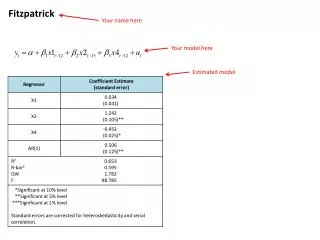
ORION AEROSPACE Static Stability Derivative Comparison All units are rad-1 Note: The MPX5 is a model aircraft designed by Mark Peters for his thesis, “Development of a Light Unmanned Aircraft for the Determination of Flying Qualities Requirements”, May 1996.
ORION AEROSPACE Structures Overview • -Basic layout of the wings • Structures matlab code • Material properties • Equipment layout • Weight breakdown • Landing gear analysis
ORION AEROSPACE Basic Layout of Wing Spar -located at the 1/4 chord Sparcaps -spruce -1/8” x 1/8” x 6.6’ Shearweb -balsa -1.5” x 1/16” x 6.6’ Ribs -balsa -spaced every 3 inches from tip -include lightening holes Added balsa at leading and trailing edge
ORION AEROSPACE Geometric Layout of rib & wing Typical rib section
ORION AEROSPACE Code • Code run using preliminary size of aircraft, load factor, and a chosen spar size • -Wing loading • Schrenk’s approximation (Raymer) • Shear force • Moment • Find centroids • Moments of inertia • Normal stress
ORION AEROSPACE WING LOADING Trapezoidal approximation Elliptical approximation
ORION AEROSPACE SHEAR FORCE
ORION AEROSPACE MOMENT
ORION AEROSPACE Normal STRESS
ORION AEROSPACE Material Properties -Normal Stress (at spar caps) = 2750psi Table taken from Spring ’99 AAE 451 report (Team WTA)
ORION AEROSPACE Internal equipment layout Equipment Volume(in3) Gear box 3 x 1.5 x 1 Motor 2.25 x 1.5 Speed Controller1.5 x 1.25 x 1 Receiver 1.75 x 1.25 x 0.75 Gyro 1.5 x 1.25 x 1.25 Data Recorder 1.75 x 2.25 x 3.25 Battery(18) 2 x 1 x 1 Servo 1.5 x 1.25 x 0.75 Interface 1.25 x 3.5 x 5.75
ORION AEROSPACE Predicted Weight Breakdown Total Weight SID5 = 163.2 (oz), 10.2(lbs)
ORION AEROSPACE Landing Gear • Conventional taildragger landing gear -Lateral separation angle of 37.7 -Located 1.2’ from nose 0.6” in front of the leading edge Method for sizing and placement of landing gear Figure 11.4 Raymer
Propulsion ORION AEROSPACE • Constraint Values for Propulsion Design • Motor Selection • Propeller Selection • Speed Controller Selection • Gearbox Selection • Battery Sizing & Energy Balance • Results from the Flight Tests
Propulsion ORION AEROSPACE • • Constraint Values for Propulsion Design • From Sizing Codes • Maximum Thrust Required = Climb Thrust = 3.35 lbf • Maximum Power Required into Air =109 Watts • Endurance Time = 13.3 minutes • Maximum Available Energy = • 1) 2592 Watts-Min. (18 Sanyo 2000mAh Ni-Cd, 1.2 Volts) • 2) 3888 Watts-Min. (18 Panasonic 3000mAh Ni-MH, 1.2 Volts)
Propulsion ORION AEROSPACE • Motor Selection -Tool : Modified Motor Code provided by Prof. Andrisani -Criteria : High Efficiency, High Power at Low Current
Propulsion ORION AEROSPACE
Propulsion ORION AEROSPACE • • Propeller Selection • Tool : Modified Gold Code provided by Prof. Andrisani • Criteria : High Efficiency, Low Power Usage, High Thrust at 25 ft/sec.
Propulsion ORION AEROSPACE • •Gearbox and Speed Controller Selection • Tool : Modified Gold Code provided by Prof. Andrisani • Criteria : Minimum Power dissipated by Controller, High Efficiency, Low RPM
Propulsion ORION AEROSPACE • • Battery Sizing & Energy Balance • Tool : Modified Motor Code provided by Prof. Andrisani & Iteration procedure to match Battery Size • Criteria : Minimum Number of Battery Cells, Minimum Energy Usage • Ni-Cd Battery : Easy to Charge and Handle. Heavy Weight and Low Capacity, Proven Battery. • Ni-MH Battery : Low Weight and High Capacity. Sensitive to Heat and Hard to Charge.
Propulsion ORION AEROSPACE • • 3 Choices to Final Propulsion Design Consideration • Common Features : MaxCim N32-13Y Motor, Maxµ35B-21 S.C. • Choice 1 : 14X8 Propeller, 3.53 Gear Ratio • Choice 2 : 14X8 Propeller, 3.75 Gear Ratio • Choice 3 : 14X10 Propeller, 4 Gear Ratio
Propulsion ORION AEROSPACE • •Final Propulsion Design Selection • Choice 1 : MaxCim N32-13Y Motor, Maxµ35B-21 S.C, 14X8 Propeller, 3.53 Gear Ratio, 18 Battery Cells • Overall Efficiency : 38.55%
Propulsion ORION AEROSPACE •Results from the Flight Tests -Main Target to Achieve is to make 12 minute Endurance -Ability to take off in 40 yards or less
M&P ORION AEROSPACE Mission & Performance • Phase Time Breakdown, Energy & Power Requirement
Cost ORION AEROSPACE Cost Analysis • Wing Test Materials ~ $90 • SID5 Materials ~ $259.95 • SID5 Electronics ~ $1125 • Man Hours (estimate) ~ 2650 • Labor ($75/hour) ~ $198,750 • Total ~ $200,125
Cost ORION AEROSPACE Price Breakdown of SID5
ORION AEROSPACE Construction -AutoCAD drawings: actual size -Component templates created -Wing construction -ribs: balsa -spar caps: spruce -shear web: balsa -leading edge: balsa -aileron construction: balsa (w/ribs) -monokote -struts