Download
1 / 48
480 likes | 483 Views
Solving Bayesian Decision Problems: Variable Elimination and Strong Junction Tree Methods. Presented By: Jingsong Wang Scott Langevin May 8, 2009. Introduction. Solutions to Influence Diagrams Variable Elimination Strong Junction Tree Hugin Architecture Conclusions.

E N D
Solving Bayesian Decision Problems:Variable Elimination and Strong Junction Tree Methods Presented By: Jingsong Wang Scott Langevin May 8, 2009
Introduction • Solutions to Influence Diagrams • Variable Elimination • Strong Junction Tree • Hugin Architecture • Conclusions
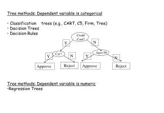
Solutions to Influence Diagrams • Chance Nodes • Decision Nodes • Utility Nodes The example influence diagram, DI I0 = Φ, I1 = {T}, I2 = {A, B, C}
Strategies and Expected Utilities DI unfolded into a decision tree. Apply average-out and fold-back algorithm. To reduce the size of the decision tree the last chance node in each path is defined as the Cartesian product of A and C, and that the utilities in the leaves are the sums of V1 and V2.
Strategies and Expected Utilities – D2 The decision tree with D2 replaced by a utility function reflecting that the policy δ2 for D2 is followed.
Variable Elimination • Compare the method for solving influence diagrams with the junction tree propagation algorithm • Similarities: • Start off with a set of potentials • Eliminate one variable at a time • Differences: • The elimination order is constrained by the temporal order • Two types of potentials to deal with • Need to eliminate in only one direction • Strong elimination order • Sum-marginalize In, then max-marginalize Dn, sum-marginalize In-1, etc
Variable Elimination • Analyze the calculations in eliminating a variable • Φ a set of probability potentials • Ψ a set of utility potentials • The product of all probability potentials multiplied by the sum of all utility potentials:
Strong Junction Tree Methods • Rely on secondary computational structure to calculate MEU and policies • Similar idea of Junction Tree Method, only here the order of elimination is constrained by the partial order • Hugin Method • Lazy Propagation Method • Creating a Strong Junction Tree • Moralize Influence Graph • Triangulate Moralized Graph • Arrange Cliques into Strong Junction Tree
Running Example Partial Temporal Order: I0 = {B}, D1, I1 = {E,F}, D2, I2 = Ø, D3, I3 = {G}, D4, I4 = {A, C, D, H, I, J, K, L}
Moralization of Influence Diagram • Remove informational links • Add a link between nodes with a common child • Remove utility nodes • Remove directional arrows
Strong Triangulation of Moral Graph • Triangulate by eliminating nodes from moral graph according to reverse of partial order imposed by influence diagram: • Nodes in Ik have no imposed order and can be eliminated in any order (ex: use min fill-in heuristic)
Strong Triangulation of Moral Graph → Partial Order: I0 = {B}, D1, I1 = {E,F}, D2, I2 = Ø, D3,I3 = {G}, D4, I4 = {A, C, D, H, I, J, K, L} Elimination Order: A, L, I, J, K, H, C, D, D4, G, D3, D2, E, F, D1, B
Strong Junction Tree Construction • Organize cliques of triangulated graph into a strong junction tree: • Each pair of cliques (C1, C2), C1 ∩ C2 is contained in every clique on the path connecting C1 and C2 • Each pair of cliques (C1, C2) with C1 closer to root R than C2, there exists an ordering of variables in C2 that respects the partial order and with the nodes in C1 ∩ C2 preceding the variables in C2\C1 • Ensures that the maximum expected utility can be computed via local message passing in the junction tree
Strong Junction Tree Construction Algorithm for generation of Strong Junction Tree • Number nodes in triangulated graph according to reverse of elimination order chosen during triangulation • Let C be a clique in the triangulated graph and v be the highest numbered node in C with neighbor node u not in C and the number associated with u < the number associated with v • If such a node v exists, then set index of C to number of v, else set index of C to 1 • Order the cliques in increasing order according to their index • This order will have the running intersection property: • To construct Strong Junction Tree: start with C1 (the root) then successively attach each clique Ck to some clique Cj that contains Sk
Strong Junction Tree Construction → Partial Order: I0 = {B}, D1, I1 = {E,F}, D2, I2 = Ø, D3,I3 = {G}, D4, I4 = {A, C, D, H, I, J, K, L} Cliques: {B,D1,E,F,D}, {B,C,A}, {B,E,D,C}, {E,D2,G}, {D2,G,D4,I}, {D4,I,L}, {D3,H,K}, {H,K,J}, {F,D3,H}
Hugin Architecture • Each clique C and separator S in Junction Tree contains a probability potential ϕ and a utility potential Ψ • Initialize Junction Tree • Assign each potential ϕ to one and only one clique C where dom(ϕ) ⊆ dom(C) • Combine potentials in each clique: • Assign unity potential to cliques with no probability potential assigned • Assign null utility potential to cliques with no utility potential assigned
Hugin Architecture • Uses message passing in the strong junction tree • Messages are passed from leave nodes towards the root node via adjacent nodes • A clique node can pass a message when it has received messages from all adjacent nodes further from the root node • Messages are stored in the separator S connecting two adjacent nodes • The message consists of two potentials: probability potential ϕS and a utility potential ΨS that are calculated as: • Note that ∑ is a general marginalization operator and is a summation for probability nodes and a max function for decision nodes. Nodes are marginalized according to reverse of partial order • Message from Cj is absorbed by Ci by:
Hugin Architecture • The optimal policy for a decision variable can be determined from the potentials of the clique or separator that is closest to root and contains the decision variable (it may be the root itself) • The MEU is calculated using the potentials in the root node after message passing has completed
Hugin Architecture Elimination Order: A, L, I, J, K, H, C, D, D4, G, D3, D2, E, F, D1, B C1 C2 C3 C4 C5 C6 C7 C8 C9
Hugin Architecture Elimination Order: A, L, I, J, K, H, C, D, D4, G, D3, D2, E, F, D1, B C1 {U1(D1)}, {P(F|D), P(D|B,D1), P(B)} {P(G|E)} {P(E|C,D)} C2 C3 C4 {U2(D3)}, {P(H|F)} {P(C|A,B), P(A)} {P(I|D2,G)} C5 C6 C7 {P(K|D3,H)} {U4(L)}, {P(L|D4,I)} C8 C9 {U3(J, K)}, {P(J|H)}
Hugin Architecture Elimination Order: A, L, I, J, K, H, C, D, D4, G, D3, D2, E, F, D1, B C1 Ψ(D1), ϕ(B,D,F, D1) ϕ(G,E) ϕ(E,C,D) C2 C3 C4 Ψ(D3), ϕ(H,F) ϕ(C,A,B) ϕ(I,D2,G) C5 C6 C7 ϕ(K,D3,H) Ψ(L), ϕ(L,D4,I) C8 C9 Ψ(J,K), ϕ(J,H)
Hugin Architecture Elimination Order: A, L, I, J, K, H, C, D, D4, G, D3, D2, E, F, D1, B C1 C2 C3 C4 C5 C6 C7 C8 C9
Hugin Architecture Elimination Order: A, L, I, J, K, H, C, D, D4, G, D3, D2, E, F, D1, B C1 C2 C3 C4 C5 C6 C7 C8 C9
Hugin Architecture Elimination Order: A, L, I, J, K, H, C, D, D4, G, D3, D2, E, F, D1, B C1 C2 C3 C4 C5 C6 C7 C8 C9
Hugin Architecture Elimination Order: A, L, I, J, K, H, C, D, D4, G, D3, D2, E, F, D1, B C1 C2 C3 C4 C5 C6 C7 C8 C9
Hugin Architecture Elimination Order: A, L, I, J, K, H, C, D, D4, G, D3, D2, E, F, D1, B C1 C2 C3 C4 C5 C6 C7 C8 C9
Hugin Architecture Elimination Order: A, L, I, J, K, H, C, D, D4, G, D3, D2, E, F, D1, B C1 C2 C3 C4 C5 C6 C7 C8 C9
Hugin Architecture Elimination Order: A, L, I, J, K, H, C, D, D4, G, D3, D2, E, F, D1, B C1 Calculate Policy: D1 use C1 D2 use C2 D3 use C3 D4 use C5 MEU: Use C1 C2 C3 C4 C5 C6 C7 C8 C9
Conclusion • We reviewed two methods for solving influence diagrams: • Variable Elimination • Strong Junction Tree Method (Hugin) • There are other methods that were not discussed: • Lazy Propagation • Node Removal and Arc Reversal