Download
1 / 1

E N D
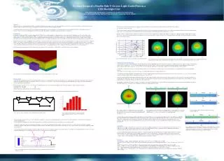
d 1 d 3 d 2 d 4 p 1 p 2 p 3 AbstractDouble-side V-groove of a lightguide plate (LGP), on each side of which transverse scalene (or isosceles) and longitudinal isosceles V-groove structures respectively constructed, can be the most efficient technique for light extraction in terms of luminance performance in an edge-type LED backlight unit (BLU) .As simulaion results reveal that at least 10% more light extraction enhancement is achieved compared to conventional medium-size edge-type BLUs. The effect of individual base angle of a transverse V-groove structure on emitting light from a LGP is investigated. The influence of pitch depth on optical performance is examined too. The relation between the propagation angles of light rays inside the LGP and their corresponding outcoupling angles from the LGP is shown in Fig. 5. (3) The gray region indicates where the designed outcouping angle should be located corresponding to the angular distribution of most light rays, entering the LGP (more than 70%) with propagation angle of ±13°~39°, are concentrated. It is not difficult to choose which first base angle as the starting point for this design process―1 = 50°. With the concern of computation time in simulation, a truncated version of the model is implemented in simulation. The dimension of LGP is of 5 × 200 × 0.7 mm. The examined first base angles 1 are of 35°, 45°, and 55°. The second base angles 2 is determined to be 5° by our previous study for double-side V-groove of a wedge-type LGP in a CCFL BLU. The simulation results, as shown in Fig. 6, consist with our analysis. IntroductionIn edge-type backlight units (BLUs), integrated light-guide plate (LGP) with its excellent capability of collimating light as well as its potential of eliminating some of the optical films, such as diffuser films, and brightness enhancement films (BEFs), once triggered a surge of research interest and activities on this issue [1-4]. But,the practical applications thus far have been limited to small-size BLUs. Cost in product development as well as technical difficulties in manufacturing may have hindered the progress of implementation. However, there is always a niche for high performance products in the display market, especially for medium-size (12”~15”) LED BLUs with double-side V-groove LGP, as shown in Fig.1. This has been the driving force behind this work. In this paper, the optical design of a LED BLU using a LGP with a concave transverse V-groove structure in the upper surface and a longitudinal V-groove structure in the bottom surface, as depicted in Fig. 1, is considered.A design algorithm based on region partition method has been developed. By this model as well as certain design principles evolved from experience and some optic laws, such as illuminance uniformity, we can reduce iterations and speed up the design cycle. Optical simulations with Advanced Systems Analysis Program (ASAP) are performed to investigate the effect of two base angles as well as depth of a transverse scalene (or isosceles) V-groove on an optimal design as well as to validate the efficiency and effectiveness of our design approach. Typical simulation results are presented. With optimal design, only one (at most two) optical film, i.e., diffuser film, is needed; the other ones can be eliminated. Optimal Design of a Double-Side V-Groove Light Guide Plate in a LED Backlight Unit Chih-Chieh Kang,Jeng-Feng Lin, Jiun-Shian Yu, Cho-Wei Chen, Shi-Fu ZengDept. of Electrooptical Eng., Southern Taiwan University, Yung-Kang,Tainan, Taiwan (a) (b) (c) Fig. 5. Outcoupling angle as a function of propagation angle inside the LGP. Fig. 6. Simulation results of angular distribution of emitting light from an edge-type BLU with double V-groove structures on a LGP using a diffuser film. having transverse scalene V-groove structure with 1st base angle 1 of (a) 55°, (b) 45°, (c) 35°, respectively, and 2nd base angle 2 of 85°. Simulation results and discussion A typical simulation result of angular distribution of emitting light from an edge-type LED BLU with double-side V-groove structures on a LGP is shown in Fig. 7. The base angles of the transverse isosceles V-groove structure is 1 = 2 = 45°. Since the depth of the transverse isosceles V-groove structure is equal to 5 m, the range of pitch spacing is between 660 m and 750 m. With no diffusion film, the light extraction efficiency is of about 77.65%. It is more than 10% light extraction enhancement compared to conventional medium-size edge-type BLUs. Compare Fig. 7 with Fig. 6(b), the effect of second base angle becomes obvious. As the angle of second base angle 2 decreases, the amount of outcoupling light with larger outcoupling angle increases. As the angle of second base angle 2 decreases, the amount of outcoupling light with larger outcoupling angle increases. The robustness of our design algorithm is demonstrated in Fig. 8. It is the “optimal” design when the base angles of the transverse isosceles V-groove structure is 1 = 2 = 47.5°, and its pitch depth equals 5 m. With no diffusion film, the light extraction efficiency is of about 77.72%. There is no obvious difference in illuminance uniformity between “with” and “without” a diffuser film, as shown in Fig. 8(a) and 8(b). However, by the observation of the angular distribution of emitting light, the distinction becomes obvious. A design of smaller second base angle will produce a group of outcoupling light with much larger outcoupling angle, as shown in Fig. 8(c). And the implementation of a diffuser film can smear the effect off, as shown in Fig. 8(d). The illuminance uniformity achieved above sometime can be illusive, especially for a LGP with V-groove structures. By an eye-like mechanism in optical simulation using ASAP developed by us [6], bright fringes arise, as seen in Fig. 8(a) for illuminance distribution of emitting light from a LGP. Fig. 1. Schematics of an edge-type LED BLU with double V-groove structures on a LGP using only one diffuser film. Design method A general-purpose ASAP ray-tracing model for a LGP with double-side V-groove structure has been developed to perform the work of optimal design. The decisive design parameters in this model include: the depth and the base angles of a transverse scalene (or isosceles) V-groove structure as well as its pitch spacings. Region partition method has been employed to achieve uniformity in terms of both luminance and illuminance. The pitch spacings of transverse V-groove are varied monotonically along the direction moving away from LEDs in each region. For simplicity, a simple design rule is applied: pitch spacingpn+1 = p n –Δx . (1) pitch widthd n+1 = d n +Δy (2) where Δx and Δy are constant increment. This is illustrated in Fig. 2. Much more complex design rules can be implemented with price of manipulation complexity, since Δx andΔy can vary by applying mathematic functions, “exp”. Fig. 9. Simulation results of Fig. 8(a) and Fig. 8(b) with “angle sorting” of light rays. Fig. 7. Angular distribution of emitting light from an edge-type LED BLU with double-side V-groove structures on a LGP using a diffuser film, having transverse isosceles V-groove structure in the upper surface with base angle 1 = 2 = 45°. Fig. 8. Simulation results of illuminance and angular distribution of emitting light from an edge-type LED BLU with double V-groove structures on a LGP, having transverse scalene V-groove structure with base angle 1 = 2 = 47.5°. (a), (c): without, (b), (d): with a diffuser film. Fig. 2. Transverse V-groove distribution with variable pitch spacing and pitch width. Fig. 3. Sampled angular distribution of light rays after light passing through the incident end surface of the LGP from a LED. A design with pitch depth of 10 m and a diffuser film employed is reexamined with our eye-like mechanism. The pitch spacing is between 500 m and 2000 m. The regular simulation result of illuminace distribution is shown in Fig. 10(a). It appears that the illuminance uniformity seems to be achieved. However, bright fringes are so distinct as the eye-like mechanism is performed. This illustrates that as the depth of the pitch is increased, the bright fringes will becomes a problem mura. That is the reason why the depth of pitch is chosen to be 5 m in our design. Of course, the smaller the pitch depth is, the better its optical performance is. Though the depths of transverse V-groove can be adjustable accordingly by continuously varying pitch spacings in our model, however, only fixed depth is considered due to the feasibility in practical implementation. For easy and effective manipulation of this model, the upper surface of the LGP is partitioned into 5 regions of unequal size for a median size BLU. To speed the design cycle and to increase luminance performance, it is crucial to first determine the first base angle 1 of the transverse V-groove structure with the consideration of angular distribution of light rays after light passing through the incident end surface of the LGP, of which propagation angle is in the range of ± 42.14° and accounts for only about 90% of light from a LED , as shown in Fig. 3. Considering the interaction between light rays inside the LGP and the transverse V-groove structure, light rays can be grouped into two: (A) light rays encountering the transverse V-groove structure indirectly, and (B) light rays encountering the transverse V-groove structure directly, as depicted in Fig. 4. Conclusion With both two base angles of the transverse isosceles V-groove structure in a LGP are determined to be 47.5°, the optimal design of double-side V-groove of a LGP in an edge-type BLU is performed. The design based on our developed algorithm has proven to be plausible in terms of illuminance performance by simulation results. The light extraction efficiency is of about 77.72% from a LGP. It is more than 10% light extraction enhancement compared to conventional medium-size edge-type BLUs. By observing the angular distribution of emitting light from a BLU with a diffuser film, a satisfied luminance performance is achieved. The influence of pitch depth, smaller is better, cannot be ignored in order to avoid the occurrence of bright fringes mura. Though the effect of second base angle on luminance might not be significant, but more work is needed to explore it and to consider the influence of a diffuser film on luminance performance of a BLU. Fig. 10. Simulation results of illuminance distribution of emitting light from an edge-type LED BLU with double V-groove structures on a LGP, having transverse scalene V-groove structure with base angle 1 = 50° and 2 = 85°, with pitch depth of 10 m, and with a diffuser film. (a) Without and (b) with “angle sorting” of light rays References [1] T. Okumura, A. Tagaya, Y. Koike, M. Horiguchi, and H. Suzuki, “ Mol. Cryst. Liq. Cryst., 418, pp. 299-313, 2004. [2] D.Feng, Y.Yen, X.Yang,G.Jin, and S.Fan, “Novelintegrated light-guide plates for liquid crystal display backlight,” J. Opt. A. Pure Appl. Opt., 7, pp. 111-117, 2005. [3] Y. Y.Chang, Y. N.Pao, C. W.Yu, and P. H.Yao, “Ultra-thin backlight module with integrated light guide film,” IDW ’06, pp. 961-964,2006. [4] Li, C. J.,Fang, Y. C., Chu, W. T., andJeng, M. J.,Prsim-pattern design for a light guide plate of a LCD backlight module, ICDL ’07 (2007) pp.119-122. [5] C. C. Huang, Optimization of Backlight Unit Design forLCD Having no Optical Film, Master thesis, STU, 2007. (in Chinese) [6] C. C. Kang, J. F. Lin, C. W. Chen, and Y. C. Wu, “Virtual mechanism for displaying viewing angle related mura of a backlight unit in simulation,” IDIM ’09, 2009.(Accepted) Fig. 4. A 2D schematic illustration of light outcoupling in an edge-type LED BLU with double V-groove structures on a LGP.