Download
1 / 50
500 likes | 606 Views
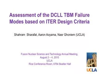
ICRF scenarios for ITER’s half-field phase. E. Lerche, D. Van Eester and JET-EFDA contributors 19th Topical Conference on RF power in Plasmas, Newport 2011. ICRF scenarios for ITER’s half-field phase.

E N D
ICRF scenarios for ITER’s half-field phase E. Lerche, D. Van Eester and JET-EFDA contributors 19th Topical Conference on RF power in Plasmas, Newport 2011
ICRF scenarios for ITER’s half-field phase E. Lerche1, D. Van Eester1, J. Ongena1, M.-L. Mayoral2, T. Johnson3, T. Hellsten3, R. Bilato4, A. Czarnecka5, R. Dumont6, C. Giroud2, P. Jacquet2, V. Kiptily2, A. Krasilnikov7, M. Maslov8, V. Vdovin9 and JET EFDA Contributors* JET-EFDA, Culham Science Centre, Abingdon, OX14 3DB, UK 1 LPP-ERM/KMS, Association Euratom-‘Belgian State’, TEC Partner, Brussels, Belgium 2 Euratom-CCFE Fusion Association, Culham Science Centre, UK 3 Fusion Plasma Physics, Association Euratom-VR, KTH, Stockholm, Sweden 4 Institut für Plasmaphysik (MPI)-Euratom Association, Garching, Germany 5 Institute of Plasma Physics and Laser Microfusion, Warsaw, Poland 6 CEA(IRFM)-Euratom Association, Saint-Paul-lez-Durance, France 7 SRC RF Troitsk Institute for Innovating and Fusion Research, Troitsk, Russia 8 Centre de Recherches en Physique des Plasmas, Association EURATOM-Conf. Suisse, Lausanne, CH 9 RNC Kurchatov Institute, Nuclear Fusion Institute, Moscow, Russia *See the Appendix of F. Romanelli et al., paper OV/1-3, IAEA Fusion Energy Conference, Daejeon, 2010
Outline - Motivation ICRF scenarios for initial operation phase of ITER (non-activated, half-field) - Summary of main results of JET experiments (H plasmas) N=1 H majority ICRH N=2 3He ‘large minority’ ICRH - Preliminary modelling of half-field ICRH scenarios H plasmas: N=1 H majority ICRH N=2 3He ‘large minority’ ICRH 4He plasmas: (Standard) N=1 H ‘minority’ ICRH Impact of H concentration (H-pellet’s) - Summary & Discussion
Outline - Motivation ICRF scenarios for initial operation phase of ITER (non-activated, half-field) - Summary of main results of JET experiments (H plasmas) N=1 H majority ICRH N=2 3He ‘large minority’ ICRH - Preliminary modelling of half-field ICRH scenarios H plasmas: N=1 H majority ICRH N=2 3He ‘large minority’ ICRH 4He plasmas: (Standard) N=1 H ‘minority’ ICRH Impact of H concentration (H-pellet’s) - Summary & Discussion
ITER half-field H plasmas (L-mode) • Plasma: ~80%H, (He3) , 2%Be, … • B0=2.65T, IP=7.5MA (L-mode) • Auxiliary power: • 16.5MW H-NBI (elec/ion = 80/20) • 15.0MW ECRH • 10MW ICRH (elec/ion = 50/50) n 3x10¹⁹/m3 L2 ICRH (?) T 8-10keV L1 ASTRA [A.Loarte, P.Lamalle]
ICRF scenarios for ITER at B0=2.65T N=1 H (~40MHz) N=1 H (either H or 4He plasmas) N=3 D (N=2 D) N=2 He3 N=2 3He (~53MHz)
Outline - Motivation ICRF scenarios for initial operation phase of ITER (non-activated, half-field) - Summary of main results of JET experiments (H plasmas) N=1 H majority ICRH N=2 3He ‘large minority’ ICRH - Preliminary modelling of half-field ICRH scenarios H plasmas: N=1 H majority ICRH N=2 3He ‘large minority’ ICRH 4He plasmas: (Standard) N=1 H ‘minority’ ICRH Impact of H concentration (H-pellet’s) - Summary & Discussion
JET experiments in H plasmas at B0=2.65T N=2 He3 N=1 H N=2 D N=3 D N=1 H majority ICRH [f=42MHz, Bo=2.65T] N=2 3He ‘minority’ ICRH [f=51MHz, Bo=2.65T] JET JET ITER ITER N=2 D N=1 He3 N=2 He3 N=1 H N=2 3He N=1 H
JET experiments in H plasmas at B0=2.65T L1=L2 L2 L1 JET • B0=2.65T (ITER), IP=1.5MA (<<ITER) • Similar Ne but lower T than ITER • ICRF power up to 6MW (ITER 10MW) • NBI: D-beams instead of H-beam (ITER non-active phase)
Outline - Motivation ICRF scenarios for initial operation phase of ITER (non-activated, half-field) - Summary of main results of JET experiments (H plasmas) N=1 H majority ICRH N=2 3He ‘large minority’ ICRH - Preliminary modelling of half-field ICRH scenarios H plasmas: N=1 H majority ICRH N=2 3He ‘large minority’ ICRH 4He plasmas: (Standard) N=1 H ‘minority’ ICRH Impact of H concentration (H-pellet’s) - Summary & Discussion
N=1 Hydrogen majority ICRH (f=42MHz) #79332: B=2.67T, f=42.50MHz TOMCAT H N=2 D e- Power absorption N=1 He3 N=2 He3 N=1 H • Initial remarks: • Low absorptivity scenario • Electron absorption dominant • No He3 !
Typical N=1 H pulse (f=42MHz) JPN 79335 • Weak energy response to RF power step (low absorbtivity) • Considerable radiation losses (DPrad / DPICRH ≈ 1/3)
ICRF Heating efficiency RF Power absorption elecs (KK3) electrons ions ions (CXRS) h = 0.3-0.4 TOMCAT Heating efficiency increases with plasma temperature Absorbed power electrons ions
PICRH dependence Central temperatures 1 PINI = 1.3MW NBI 2 PINIs = 2.6MW NBI Ti Te ~0.1keV/MW ~0.1keV/MW Poor performance compared to similar (H)-D ICRF expts. B0=2.7T (H)-D (JET) ~1keV/MW
RF acceleration (NPA) Horizontal neutral particle analyzer (KR2) PRF=2.5MW PRF=5MW H H Very modest tails if compared with minority ICRH experiments • No clear effect of ICRF on D distribution • (Hints of fast H with E~200keV in KF1) SKIP if NEEDED
Outline - Motivation ICRF scenarios for initial operation phase of ITER (non-activated, half-field) - Summary of main results of JET experiments (H plasmas) N=1 H majority ICRH N=2 3He ‘large minority’ ICRH - Preliminary modelling of half-field ICRH scenarios H plasmas: N=1 H majority ICRH N=2 3He ‘large minority’ ICRH 4He plasmas: (Standard) N=1 H ‘minority’ ICRH Impact of H concentration (H-pellet’s) - Summary & Discussion
N=2 He3 ICRH (f=51MHz) #79357: B=2.66T, f=51.50MHz TOMCAT X[3He]=5% Power absorption N=1 H N=2 He3 N=2 D N=3 D • Initial remarks: • Low absorptivity scenario • Largely dominant electron heating at low X[He3] • Ion heating enhanced for higher X[He3] • D-beams: N=2 / 3 parasitic absorption
Typical N=2 He3 pulse 4Hz JPN 79359 ~4MW X[He3] RTC ~2MW elec elec + ion • X[3He]<20%: only elec heating • X[3He]>20%: elec + ion heating • Large radiation losses (DPrad / DPICRH ≈ 1/2)
ICRF heating efficiency Global heating efficiency (Wpla) JPN 79359 nkTe+nkTi TOMCAT • 2x larger heating efficiency at • X[3He]=20% (w.r.t. 5-10%) • Efficiency increase is due to • enhanced ion absorption total Absorbed power ions elecs
X[He3] dependence(2 PINIs , PICRH ~ 2.5MW) Overall performance increase (PICRH ~ 2.5MW) • (Equilibrium) plasma energy and temperature increase with X[3He]
PICRH dependence (1 PINI, X[He3]=10-18%) Central temperatures Ti Te ~0.25keV/MW ~0.2keV/MW • Better performance than N=1 H maj. expts. • Poor performance compared to similar • (H)-D ICRF expts. B0=2.7T (H)-D (JET) ~1keV/MW
RF acceleration (NPA) Horizontal NPA (KR2) He3 D • Dominant 3He RF acceleration for E<160keV • Dominant (N=3) RF acceleration of D (beam) ions for E>160keV [V.Kiptily, to appear in PPCF]
Impurities: N=1 H vs. N=2 He3 Ni Be Higher impurity content in N=2 3He discharges Bolom C6 C4 • Higher radiation from plasma edge / divertor • Confirmed by 2D bolometric tomography [A.Czarnecka, to appear in PPCF]
Summary of JET experiments N=1 H ICRH • Low heating efficiency (h = 0.3 - 0.4) • Dominant electron heating: pe 2 x pi (LD + TTMP) • Modest H acceleration (up to 50keV) registered by NPA • Negligible parasitic N=2 D absorption • Poor global heating: ~0.1keV/MW • Considerable plasma-wall interaction (DPrad/DPICRH ≈ 1/3) N=2 He3 ICRH • Low heating efficiency (h = 0.15 – 0.4, increasing with X[He3]) • Largely dominant electron heating for low X[He3] (mainly LD + TTMP) • Ion absorption proportional to X[He3]: dominant for X[He3] > 20% • Fast He3 (up to 250keV) detected by NPA • Clear parasitic D absorption with PNBI>5MW • Poor global heating: ~0.2keV/MW • Strong plasma-wall interaction (DPrad/DPICRH ≈ 1/2, impurities, etc…)
Outline - Motivation ICRF scenarios for initial operation phase of ITER (non-activated, half-field) - Summary of main results of JET experiments (H plasmas) N=1 H majority ICRH N=2 3He ‘large minority’ ICRH - Preliminary modelling of half-field ICRH scenarios H plasmas: N=1 H majority ICRH N=2 3He ‘large minority’ ICRH 4He plasmas: (Standard) N=1 H ‘minority’ ICRH Impact of H concentration (H-pellet’s) - Summary & Discussion
Preliminary ITER modelling • Objectives: • - Intuitive picture of relative RF absorptivity • (SPA) of the various heating scenarios • - Parametric scans for preliminary optimization • More ‘rigorous’ numerical efforts • [R. Budny, IAEA2010, to appear in NF2011] 1D TOMCAT code [Van Eester, PPCF98]
Outline - Motivation ICRF scenarios for initial operation phase of ITER (non-activated, half-field) - Summary of main results of JET experiments (H plasmas) N=1 H majority ICRH N=2 3He ‘large minority’ ICRH - Preliminary modelling of half-field ICRH scenarios H plasmas: N=1 H majority ICRH N=2 3He ‘large minority’ ICRH 4He plasmas: (Standard) N=1 H ‘minority’ ICRH Impact of H concentration (H-pellet’s) - Summary & Discussion
Fundamental H majority ICRH (42MHz) E+ electric field TH 8keV w=WH • E+ 0 @ w=WH (‘screening’) • Low absorptivity scenario (m = 0.3 - 0.4) • Dominant electron heating (broad absorption) • Higher TH helps ion absorption • Possible 3He absorption (if present) TH 25keV
Parametric scan n=34 (0pp0) L-mode 2: T =8/10keV ITER ITER • Higher TH yields higher absorption (ions) • Higher ne yields higher absorption (elecs) • pe = pi @ TH 20keV
N=2 3He ‘minority’ ICRH (53MHz) E+ electric field X[3He]=4% w=WH w=2WHe3 • Larger E+ at w=2WHe3 • Low absorptivity scenario (m = 0.25 - 0.4) • Dominant electron heating (broad absorption) • Ion heating enhanced at higher X[3He] • Possible N=1 H (N=2,3 D) absorption X[3He]=25%
Parametric scan n=34 (0pp0) L-mode 2: T =8/10keV ITER ITER • Higher X[3He] yields higher absorption (ions) • Higher ne yields higher absorption (elecs) • pe = pi @ X[3He] 30%
Do we have an ICRH scenario for H plasmas? N=2 H majority ICRH at 1/3 nominal field (B0=1.8T) E+ electric field N=2 H (N=3 D) pH = 70% pe = 30% • Full single-pass absorption (m=1) • Dominant ion heating • But ECRH out of range, confinement (?) • Could be used for fast particle studies
Outline - Motivation ICRF scenarios for initial operation phase of ITER (non-activated, half-field) - Summary of main results of JET experiments (H plasmas) N=1 H majority ICRH N=2 3He ‘large minority’ ICRH - Preliminary modelling of half-field ICRH scenarios H plasmas: N=1 H majority ICRH N=2 3He ‘large minority’ ICRH 4He plasmas: (Standard) N=1 H ‘minority’ ICRH Impact of H concentration (H-pellet’s) - Summary & Discussion
N=1 H–4He minority ICRH (42MHz) n=34 (0pp0) L-mode 2 E+ electric field w=WH • Good absorption scenario (m = 0.7 – 1.0) • Dominant ion heating (for moderate X[H]) • Ion absorption decreased at higher X[H]
N=1 H–4He minority ICRH (42MHz) L-mode 2: T =8/10keV L-mode 1: T =4/5keV n=34 (0pp0) n=34 (0pp0) n=60 (0p0p) • Ion absorption is reduced at higher X[H] (‘screening effect’) • This effect is stronger at lower temperatures (L-mode 1): • Operating at high k// phasing (0p0p) helps • Accounting for tail formation does not alter the behaviour at high X[H] • No MC absorption (1D and 2D)
N=1 H–4He minority ICRH (42MHz) Comparison with 2D wave codes EVE code [R.Dumont, NF2009] E+ E+ X[H]=5% X[H]=45% Pabs Pabs • Electron absorption slightly overestimated in 1D calculations • Unlike for the H plasmas (touchy), for the better absorbing (H)-D scheme 2D calculations are converged
SPA vs. heating efficiency Simple multi-pass model mloss=0.1 mpla=0.5 (4He plasmas) mloss=0 Power ITER JET (H plasmas)
Summary of ITER modelling N=1 H majority ICRH • Moderate absorptivity (m~0.5) → significant PWI? [seen in JET] • Dominant electron heating [seen in JET] • Increasing temperature favours ion heating [seen in JET] but pe=pi @ 25keV • Increasing density favours overall heating (electron heating dominant) N=2 3He–H ICRH • Low absorptivity (m~0.3) significant PWI? [seen in JET] • Largely dominant electron heating except for high X[He3] [seen in JET] • Increasing X[He3] favours ion heating [seen in JET] but pe=pi @ X[He3]~30% • Increasing temperature has small effect • Increasing density favours overall heating (electron heating dominant) N=1 H-4He ICRH • Good single-pass absorption (m>0.7) with dominant ion heating (X[H]<25%) • ICRF efficiency lower for larger X[H], partic. at lower temperature (L mode-1) • This effect can be compensated with higher k// phasing (0p0p)
Final remarks • H plasmas: • Both ICRF scenarios proposed for ITER’s half field phase in H suffer from low power absorptivity with dominant electron heating: • - N=1 H majority requires high plasma temperatures • - N=2 3He requires large X[3He] for efficient ion heating • This DOES NOT mean that they are not suited for the commissioning of the ICRF system, but the power may be limited (enhanced PWI) • One possible ICRF scenario with good ion absorption is N=2 H majority at 1/3 of the nominal B0 (but ECRH is out of range) • 4He plasmas: • (H)-4He minority ICRH is OK for moderate X[H] (<40%) • At higher X[H] the ion absorption is jeopardized, particularly at low T • Operating at higher k// phasing (e.g. 0p0p) helps recovering good absorption in general (but lower coupling)
Final remarks • Wave modelling: • Low absorption H-plasma scenarios require further modelling (touchy!) • (H)-4He ICRF scenario well converged but further simulations at high X[H] welcome • Integrated scenario modelling: • Use experimental heating efficiencies / SPA’s obtained for assessing which DT can actually be expected in ITER’s half-field H-plasma phase • Use realistic power absorption profiles in all cases (broader elec. absorption) • Experiments: • High X[H] ICRH experiments in 4He plasmas (B0=2.65T, f=42MHz)
Impurities: N=1 H vs. N=2 He3 (KS3) Bolom Zeff Be Cr Ni Higher impurity content in N=2 3He discharges [A.Czarnecka, to appear in PPCF]
Impurities: N=1 H vs. N=2 He3 (KT2/7) VUV spectroscopy (KT2/KT7) C4 C6 N=1 H N=2 3He • Higher radiation losses in N=2 3He scenario come from plasma edge / divertor • Confirmed by 2D bolometric tomography
Effect of antenna phasing Fundamental H majority ICRH (42MHz) coax • Larger k// yields higher absorption • pe / pi roughly independent of k// coax [A. Messiaen NF2010]
Effect of antenna phasing Fundamental H majority ICRH (42MHz) X[3He]=4% • Low X[3He]: • Larger k// yields higher absorption (elecs only) coax X[3He]=30% • High X[3He]: • Low k// → ion heating • Large k// → elec. heating coax
Plasma dilution N=1 H majority ICRH Effect of H dillution (4He contamination) (PICRF=5MW) Wdia NPA on H no NBI 1 PINI no NBI 1 PINI X[4He] X[4He] • Preliminary modelling shows same tendency (but weaker) • Important to re-assess experimentally
RF acceleration (NPA) Horizontal NPA (KR2) 3He D • Relatively modest acceleation of 3He ions (E<160keV) (hints on KF1 E<260keV) • Clear RF acceleration of D (beam) ions above beam source energy
RF acceleration (ion losses) Scintillator probe (KA3) [V.Kiptily] t=46s D 3He • Main losses come from RF accelerated D beam ions • Small fast 3He losses (No hints fast 3He detected by g-spectroscopy)
Simple comparison with other scenarios N=1 H majority DT/DP 0.1keV/MW H minority in D (ILA) N=2 He3 DT/DP 0.2keV/MW N=1 D majority (B0=3.3T, f=25MHz) DT (keV) ~1keV/MW PICRH(MW) ~0.5keV/MW