Download
1 / 48
1.01k likes | 2.37k Views
Cincinnati, Ohio USA Diesel Engines for NFPA-20 Fire Protection Applications www.clarkefire.com. Clarke Engine with Pump Ready Base, Driveshaft, and Cooling Loop. . NFPA 20 – Engine Type. Diesel Engines for fire pump drive shall be of the compression ignition type.

E N D
Cincinnati, Ohio USA Diesel Engines for NFPA-20 Fire Protection Applications www.clarkefire.com
Clarke Engine with Pump Ready Base, Driveshaft, and Cooling Loop.
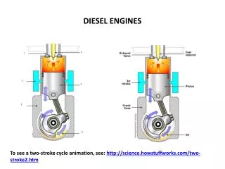
NFPA 20 – Engine Type • Diesel Engines for fire pump drive shall be of the compression ignition type. • Spark-ignited internal combustion engines shall not be used. (i.e. natural gas, propane or gasoline)
NFPA 20 - Engine Ratings • Rated at SAE Conditions 77F (25C) and 300 ft (91 m) above sea level. • Engines must have at least a 10% reserve in horsepower. (This is a UL-FM requirement and all UL-FM engine ratings reflect this requirement). • Engines must be derated for Altitude and Temperature. • 3% Derate for every 1000 ft (300 m) above 300 ft (91 m). • 1% Derate for every 10F (5.6C) above 77 F (25C).
NFPA 20 – Instrumentation & Control • Engines shall be regulated to have no more the 10% speed difference between shutoff and maximum load. (Defined as droop). • Engines shall be provided with an overspeed shutdown at 20% above rated engine speed with a manual reset. (Only overspeed shutdown or a signal from the diesel controller will shut down an engine.)
Overspeed Setting Verification To verify the engine overspeed setting and function without overspeeding the engine, follow this procedure: • Start engine manually from the controller while holding the overspeed verification switch in the ‘up’ position. Observe the shutdown RPM. • Test switch returns to normal position when released. • Reset the overspeed switch on the engine instrument panel and restart the engine from the controller to verity normal operation. • EXAMPLE: Rated engine speed: 2100 rpm Overspeed setting: 2520 rpm (120% 2100 rpm) Verification shutdown: 1688 rpm (67% of 2520 rpm)
NFPA 20 – Instrumentation & Control • Main battery contactors supplying current to the starting motor shall be capable of manual mechanical operation to energize starting motor. • Manual toggles are provided on the Clarke instrument panel and additionally manual start contactors for only the JW6H & JX6H series engines.) • Clarke electric starting standard; • One (1) starter on JW6H, JX6H units. • Two (2) starters on JU4H, JU6H units.
NFPA 20 – Instrumentation & Control Electronic Engines • Engines with an electronic control module (ECM) shall have an alternate ECM wired to produce full power in the event of primary ECM failure. • There shall be an ECM Selector Switch to transition from the primary ECM to the alternate ECM. • A visual indicator shall show when the engine is running with the alternate ECM. (On both the engine panel and on the diesel controller)
NFPA 20 – Instrumentation & Control Electronic Engines • Any sensor necessary for the function of the ECM shall have a redundant sensor that shall operate automatically in case of failure. • A signal shall be provided to the controller for fuel injector failure and low fuel pressure.
NFPA 20 – Instrumentation & Control • Each engine shall be provided with two storage battery units. • Charge batteries for 24 hours before installation. • At 40F (4.5C) each battery shall have twice the capacity sufficient to maintain 3 minute attempt-to-start cycle (15 seconds of cranking and 15 seconds of rest in six consecutive cycles).
NFPA 20 – Instrumentation & Control • There should be two means for recharging the storage batteries. • The alternator on the engine is one source. • The battery chargers in the controller is the other source.
NFPA 20 – Engine Cooling • The engine cooling system shall be of the closed-circuit type. • Heat exchanger type • Radiator type
NFPA 20 – Engine Cooling • Cooling water shall be piped through a threaded rigid pipe from the discharge of the pump to the inlet of the heat exchanger. • It is not permitted to use flexible tubing attached to the cooling loop.
NFPA 20 – Engine Cooling • The outlet for the wastewater coming from the heat exchanger shall be one size larger then the inlet. • The wastewater shall be discharged into a visible open waste cone. • Discharge can go back to a suction reservoir provided a visual flow indicator and temperature indicator are installed.
NFPA 20 – Engine Cooling • Heat exchanger standard equipment. • Sea water or fresh water; sacrificial anode optional. • Engines are shipped without coolant. • Cooling water line (cooling loop) shall have a manual by-pass. • Cooling water line and by-pass shall include: • indicating manual shutoff valve • approved flushing-type strainer • pressure regulator • automatic valve • second indicating manual valve or check valve • pressure gauge
Engine Coolant • Water, ethylene glycol, inhibitor coolant mixture. 50% water 50% coolant. • Coolant to conform to ASTM D4985. • Heat transfer • Corrosion resistance • Prevents scale and sludge build up • Provides freeze and boil over protection • Pre-mix before installing in engine to prevent premature engine heater failure.
NFPA 20 – Engine Cooling • Coolant heater is the only AC power on engine; Separate AC junction box required. Do not use controller AC for power supply. • Add coolant mixture before applying AC power. • All heaters single voltage; Optional AC voltages available - location specific. • Engine coolant maintained at 120F (49C).
NFPA 20 – Engine Protection • The engine shall be protected against possible interruption of service through explosion, fire, flood, earthquake, rodents, insects, windstorm, freezing, vandalism and other adverse conditions. • Application: The engine must be installed inside or protected from the weather and low temperature.
NFPA 20 – Air Requirements • The minimum ambient temperature for the pump room is 40F (4.5C). • The maximum temperature for the pump room is 120F (49C) at the air cleaner inlet with the engine running at rated load.
NFPA 20 – Air Requirements • Inlet louver and ventilating system must: • Maintain 120F (49C) in the room • Supply adequate air for engine combustion • Adequate air for ventilating radiated heat; both engine & exhaust system. • (Radiator Cooled Units shall be ducted outdoors in a manner that will prevent recirculation and requires more air for combustion and radiated heat removal.)
NFPA 20 – Fuel Tank Arrangement • The fuel tank is sized for 1 gal/HP (5.07 liter/kW) plus 10% (5% for expansion and 5% for sump). • The fuel tank shall be reserved exclusively for the fire pump diesel engine. • There shall be one fuel tank per engine.
NFPA 20 – Fuel Tank Arrangement • The fuel tank shall be located above ground. • The fuel tank outlet shall be located so that its opening is no lower than the level of the engine’s fuel transfer pump. • In sites where temperatures below 32F (0C) could be encountered, the fuel tank shall be located in the pump room.
NFPA 20 – Fuel Arrangement • The diesel engine must use clean #2 diesel. • #1, blended fuel, or jet fuel have a lower cetane ratings, which reduces the power output of the engine compared with the listed power. • Bleed air from fuel lines before starting.
NFPA 20 – Fuel Arrangement • Fuel supply and return lines shall be flame-resistant reinforced flexible hose. • Fuel piping shall not be galvanized steel or copper. • There shall be no shut-off in the fuel return line to the tank. • The grade of fuel oil shall be indicated on the fuel tank by letters that are a minimum of 6 in (152mm) in height and in contrasting color to the tank.
NFPA 20 – Engine Exhaust • Each engine shall have an independent exhaust system. • A flex connector shall be used between the engine and the exhaust pipe. • The flex connector shall not be used for misalignment. (The purpose of the flex is to allow for thermal expansion and for isolating engine vibration from the rest of the exhaust system.)
NFPA 20 – Engine Exhaust • Back pressure in the exhaust system shall not exceed the engine’s limit. • The exhaust sizing program on the Clarke website can calculate the back pressure) • Building supported; not engine supported • Insulation wrap the exhaust systems in-room components. • Rain cap on outlet if necessary; tight connections. • Exhaust system shall terminate outside where hot gases and sparks are discharged to a safe location.
NFPA 20 – System Operation • Engines shall be started no less than once a week and run for no less than 30 minutes. • The fire pump shall be started and brought up to rated speed without interruption within 20 seconds.
NFPA 20 – System Operation • Batteries shall be kept charged at all times and tested frequently (weekly test) to determine condition. • Only distilled water shall be used. • Battery plates shall be kept submerged at all times. • Fuel storage tanks shall never be less then 50% capacity.
Basic Information – Regarding Clarke Diesel Fire Pump Drivers
NFPA 20 – System Operation • Oil Viscosity and Grade Specification • JU4H/JU6H/JW6H/JX6H Series engines have a break in oil for the first year, afterwards require SAE 15W-40 • All engines are shipped with oil, unless the engine is shipped via airfreight.
Start Up Procedure • Checklists on web-site for: • Engine Installation • Pre-Start-up • Start-Up • Clarke Service Dealer locator on web-site. • Warranty: Engine 24 mo./ Clarke components 12 mo. • Special preparation for long term storage. • Service parts shown on web-site.
Installation Inspection • Engine Pump Alignment Check • Unit properly secured & grouted • Control wiring connected to junction box • Batteries serviced and charged 24 hours; connected to the engine
Installation Inspection • Cooling water connections properly installed on engine heat exchanger, both inlet and outlet; water solenoid operational. • Exhaust System properly sized and connected • Cooling System filled to proper solution of premixed water and coolant conditioner.
Installation Inspection • Add engine oil to proper level • Fuel lines (supply and return) connected to tank and engine • Fuel tank filled with clean #2 diesel, drain water and sediment from tank • Engine jacket water heater connected to correct AC Power • Air inlet filter installed on engine. Fresh air supply adequate for engine combustion and room ventilation.
Start Up Inspection • Installation Inspection Checklist Verification • Manual start at engine panel • Manual start at controller • Cooling water line solenoid operation • Engine panel gauges operation • No leaks: fuel, water, exhaust • High coolant temperature alarm • Low oil pressure alarm • Overspeed shutdown verification
Clarke Websitewww.Clarkefire.com Current Models I & O Data Emission Data Exhaust Sizing Operations Manual Spare Parts Illustration Power Curves Installation Drawings Contact List Wiring Diagrams Technical Manual Service Dealer Directory