Download
1 / 30
300 likes | 520 Views
Orbit Distortion in EMMA. David Kelliher ASTEC/CCLRC/RAL UKNF, 3 rd October, 2007. Contents. Short EMMA overview Orbit Distortion in EMMA Orbit correction Local orbit correction Conclusions. EMMA overview. E lectron M odel of M any A pplications.

E N D
Orbit Distortion in EMMA David Kelliher ASTEC/CCLRC/RAL UKNF, 3rd October, 2007
Contents • Short EMMA overview • Orbit Distortion in EMMA • Orbit correction • Local orbit correction • Conclusions
Electron Model of Many Applications • A design and construction project for a 10-20 MeV electron accelerator. • It will be an entirely experimental machine used to learn how to design NS-FFAGs for a variety of applications, in particular for muon acceleration in a neutrino factory. • It will be built at Daresbury Lab using ERLP as the electron injector.
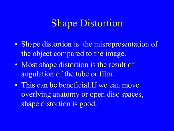
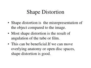
EMMA design principles • Avoid Resonance by (a) Symmetry – all cells identical (b) Linear Magnets – non linear effects weak. • Accelerate rapidly: minimise resonance effects due to magnet errors etc. • Keep horizontal aperture small J. Scott Berg – The EMMA lattice , FFAG07, Grenoble, April 12-17 2007
EMMA parameters Value 1020 MeV 1020 MeV 42 F/D Doublet 394.481 mm 16568.202 mm 13 A 5-20 mm rad (norm.) 3000 mm mrad (norm.) 3 cm 16-32 pC single bunch 1,5,20 Hz 1.3 GHz 1.295981 to 1.301554 20-120 kV/cavity 19 Parameter Kinetic Energy range Injection Number of Cells Lattice Cell length Circumference Average beam current Injected emmittance Model acceptance Orbit Swing Bunch Charge Repetition Rate RF Frequency RF Frequency Range RF Voltage Number of RF cavities Neil Bliss – EMMA status & overview , FFAG07, Grenoble, April 12-17 2007
EMMA Layout Neil Bliss – EMMA progress update , Sept 27th 2007
EMMA ring 21 cells, each has: 2x D magnet2x F magnet 84 magnets in main ring Ben Shepherd – EMMA magnet design , FFAG07, Grenoble, April 12-17 2007
EMMA magnets • The EMMA doublets, D and F, are offset quadrupoles.
Magnet prototypes • Measurements of magnets being undertaken at present by Tesla Engineering • Horizontal sliders are on site Neil Bliss – EMMA progress update , Sept 27th 2007
MADX model of EMMA • The quadrupoles are modelled as combined function RBENDS. • Pole faces of RBENDs rotated to get correct angle with reference trajectory. • Magnet and drift lengths adjusted to account for horizontal excursion of reference trajectory. • Lattice functions calculated by this model are consistent with tracking code results. • Errors in the magnet horizontal (=50mm) and vertical (=25mm) position simulated by using the MADX function EALIGN.
Polymorphic Tracking Code • PTC is a kick code, allowing symplectic integration through all accelerator elements • Inherently based on a map formalism • New subroutines were written to simulate acceleration in EMMA. • PTC can be started with a MADX lattice.
Vertical tune and closed orbit distortion (MADX) • Vertical tune passes through many integer resonances. • One seed used to simulate random alignment errors • Peaks in orbit distortion close to integral tunes • Require rapid acceleration to avoid sitting on these integer tune peaks
Vertical Distortion at rf cavities during acceleration (PTC)
Orbit Distortion summary • While there are peaks in closed orbit distortion near the integral tunes (black curve), when acceleration is included, this correlation is not evident (red curve). • We may surmise that the beam does not see the effects of resonance, instead the distortion is due to the random kicks imparted by the quad misalignment [1]. • S. Machida and D.J. Kelliher, ‘Orbit and optics distortion in fixed field alternating gradient muon accelerators’,submitted to Phys. Rev. STAB
Failure of Harmonic Correction • Effect of kicker varies since the phase advance between the kicker and any point in the lattice changes as the momentum increases. • Therefore, conventional harmonic correction of error source with kickers is not possible in a nonscaling linear FFAG.
Optimising Initial Conditions • It was found that a reduction in the orbit distortion could be made by changing the initial co-ordinates (x,x’,y,y’). • In general, the closed orbit at the injection energy do not give optimal coordinates for the “accelerated orbit”.
Optimise initial (y,y’) Vertical orbit distortion rms reduced from 2.67mm to 0.63mm
One Corrector magnet Vertical orbit distortion rms reduced from 2.67mm to 0.64mm
Orbit Correction Introduction • Ability to move magnets perpendicular to the beamline in the horizontal plane allows horizontal corrections to be made. • Vertical adjustments to the magnets may also be made. • There will be 2 BPMs per cell, providing both horizontal and vertical displacement measurements. • No BPMs will be placed in those long drifts with an RF cavity.
BPMs and vertical kicker location Neil Bliss 3/4/07
MADX cell schematic Simulated kickers D F D F BPM
Infer magnet misalignments from kicker strengths • Misalignment of quadrupole j can be expressed as a kick j • Orbit position measured at ideal BPM i is the sum of these kicks. • MADX CORRECT module finds the set of k that best restores target orbit. • Kickers are placed in the middle of divided magnets. Assume k j.
Conclusions • The problem of orbit correction in EMMA has been studied using MADX and PTC. • Orbit correction is problematic in EMMA because (a) corrector magnets cannot vary over rapid acceleration cycle (b) tune varies rapidly with momentum, therefore phase between corrector magnets and monitors varies. • It will be necessary to correct misalignments locally. Sliders facilitate this in the horizontal plane. • The initial coordinates should be optimised to reduce orbit distortion. • In the case of ideal BPMs, magnetic displacements can be calculated when the total tune is not close to integer