Download
1 / 14
140 likes | 234 Views
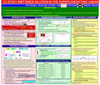
Experimental proposal to study emittance growth in the existing ATF EXT. Seryi, M. Woodley, and F. Zhou SLAC. Thank J. Amann, S. Seletskiy, C. Spencer for magnetic modeling and field fitting. 09/05/07. Outline.

E N D
Experimental proposal to study emittance growth in the existing ATF EXT • Seryi, M. Woodley, and F. Zhou SLAC Thank J. Amann, S. Seletskiy, C. Spencer for magnetic modeling and field fitting. 09/05/07
Outline • Motivation: to look for emittance growth source, and check how well the coupling correction… • Field map of the QM7 and BS1X • Generation of local bumps in the EXT and observed effects. • Close the ring orbit • Hardware requirements: an additional vertical corrector only. 09/05/07
nominal position nominal position x (x - 0.0855) (m) x (x - 0.0855) (m) Field map of QM7 and BS1X QM7 By Nominal position By, Bx Bx X (m) BS1X BS1X By Bx
EXT local bump generation BH1x(ZX1x) kicker1 QM5 QM7 BS2X BS1X QM6 BS3X ZV1X QD1X 09/05/07
More close… BH1x(ZX1x) QM5 QM7 BS2X zH9 zv9 kicker1 BS1X BS3X QM6 ZV1X QD1X 1 H corrector, which maybe ready by Naito’s group 1 V corrector, which needs to be installed 09/05/07
Either x or y offset: vertical normalized emittance growth(W/o any correction) • Either x or y offset in the existing EXT channel • Includes QM7+BS1X multipoles X=0 (nominal) Y=0 (nominal) y (nm) y (nm) X (mm) Y (mm) 09/05/07
Combined x and y offset: vertical emittance growth • Combined x and y offset in the EXT channel • QM7+BS1X multipoles. x w/o correctionx w/ correction y (nm) y (nm) 40 30 X=5 mm Y=1 mm X (mm) Y (mm) 09/05/07
Vertical phase spaces at EXT end x/y=0/0, no multi x/y=-5/1mm, w/o correction x/y= 5/1mm, w/o correction x/y=0/0,no multi x/y=5/0mm, w/o correction x/y=0/1mm, w/o correction x/y=0/0,no multi x/y=5/1mm, w/o correction x/y=5/1mm, w/ correction y’ y’ y y 09/05/07
Close the ring orbit QM12 QM7 kII QM10 QM8 QM5 kicker1 zV10 zH9 zH10 zv9 ZV11 QM6 QM9 wiggler off ZH11 QM11 H corrector (probably already ready by Naito’s group) V corrector, which needs to be installed 4-6mm Bump generated at QM7 at EXT: X=5mm y =1.5mm 09/05/07
Beam experiment • Observe the effects vs different bump amplitude; it can help us to understand the emittance growth source, and also how well the coupling correction: • Only x or y bumps • W/o correction • W/ correction • Combined x+y bumps • W/o correction • W/ correction • Total 6 correctors needed to generate local bumps; 4 correctors (2 H and 2 V) already exist, another H corrector probably already exists. 09/05/07
H corrector, installed by Naito group by Summer 2007? V corrector, which needs to be installed 09/05/07
Stripline kicker test layout Suggest to install V corrector for this test H corrector, installed by Naito group? 09/05/07
Requirements • Suggest to install 1 vertical corrector only assume strip-line kicker experiment installed all other horizontal correctors by summer 2007. • Corrector parameters: • Horizontal 5 mm offset • 1.5mrad (max); • B*L=6E-3 T.m; B~0.14 T assume L=5cm (probably is ready by the Naito experiment) • Vertical offset 1.5 mm offset • 0.3 mrad (max) • B*L=1.3E-3 T.m; B<0.03 T assume L=5 cm (suggest to install it) • Spaces look available but need check with KEK • Strip-line Kicker experiment: • Bending angle: 9mrad(max) • Effective length 100mm, and 0.4 T (max) • Power supply: 50A(MAX), 10V(pulse) 09/05/07
Summary • Initial y is 30 nm. Final emittance and phase spaces are measured at the existing EXT end. No magnet errors employed except the QM7 and Septum1 multipoles. • Tracking results: • At the nominal position: only x-offset does not create vertical emittance growth while only y-offset create vertical emittance growth w/o corrections. • Combined both x and y offsets create severe vertical emittance growth w/o corrections; combined offsets x/y=5/1mm and 5/1.5mm can create 30% and 50% vertical emittance growth after all corrections. • The beam test will be helpful to understand the emittance growth source and also how well the coupling correction. • What we require: • Suggest to install 1 more vertical corrector assume the stripline experiment installed other H correctors. • Beam time: initially, probably two shifts (test shift for bump generation and calibration, and 2nd shift for data taking). 09/05/07