Download
1 / 47
470 likes | 609 Views
Status of the SPL cryo-module development (report from WG3). V.Parma, TE-MSC (with contributions from WG3 members). Outline. Introduction New orientation and work organisation Layout studies and machine sectorisation (vacuum+cryogenics) Recent advances: Supporting schemes Cryogenics

E N D
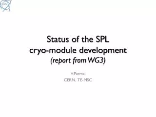
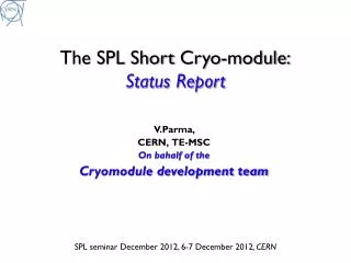
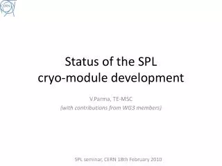
Status of the SPL cryo-module development(report from WG3) V.Parma, TE-MSC (with contributions from WG3 members)
Outline • Introduction • New orientation and work organisation • Layout studies and machine sectorisation (vacuum+cryogenics) • Recent advances: • Supporting schemes • Cryogenics • Summary
Layout injector complex SPS PS2 ISOLDE PS SPL Linac4
The SPL study at CERN • R&D study for a 5 GeV and multi MW high power beam, the HP-SPL • Major interest for non-LHC physics: ISOLDEII/EURISOL/Fixed Target/Neutrino Factory ~500 m 5GeV 110 m 0.79 GeV 186 m 1.4 GeV ~300 m 2.5 GeV 0 m 0.16 GeV High b cryomodules Ejection 20 x 3 b=0.65 cavities 6 x 8 b=1 cavities 5 x 8 b=1 cavities High b cryomodules High b cryomodules Medium b cryomodule Debunchers To fixed target/μ factory Ejection From Linac4 12 x 8 b=1 cavities to Eurisol Length: ~540 m TT6 to ISOLDE HP-SPL beam characteristics
The SPL study: new orientation New objective of the SPL study: Up to 2013: • Focus on R&D for key technologies for the high intensity proton source (HP SPL) In particular: • Development, manufacture and test of high-gradient β=1, 5 cellules ,704 MHz cavities • Development, manufacture and test of RF couplers • Testing of a string of 4 β=1 cavities in machine-type configuration: • Housed in helium vessels • Equipped with tuners • Powered by machine-type RF coupler • Need for a short cryomodulefor testing purposes
Short cryo-module: Goal & Motivation Goal: • Design and construct a ½-lenght cryo-module for 4 β=1 cavities Motivation: • Test-bench for RF testing on a multi-cavity assembly driven by a single or multiple RF source(s) • Enable RF testing of cavities in horizontal position, housed in their helium tanks, tuned, and powered by machine-type RF couplers • Validate by testing critical components like RF couplers, tuners, HOM couplers in their real operating environment Cryomodule-related goals: • Learning of the critical assembly phases: • preparation of a long string of cavities in clean room • alignment/assembly in the cryostat; • Proof-of-concept of the innovative supporting of cavities via the RF couplers • Explore cryogenic operation issues
Planned supplies for β=1short cryo-module In blue, recent changes
Relevant events since last collaboration meeting • Workshop on cryogenic and vacuum sectorization of the SPL • CERN, 9-10 Nov.2009, http://indico.cern.ch/conferenceDisplay.py?confId=68499 • 22 participants from CEA, IPN Orsay, FNAL, ORNL, JLAB, SLAC, DESY, ESS, and CERN • Review of SPL RF power couplers • CERN, 16-17 March 2010, http://indico.cern.ch/conferenceTimeTable.py?confId=86123#20100316 • 24 participants from CEA, IPN Orsay, BNL, FNAL, ANL, JLAB, DESY, Lancaster Univ., Uppsala Univ., and CERN • Intermediate meetings of the WG3: • minutes on CERN EDMS • Cryomodule documentation on https://twiki.cern.ch/twiki/bin/view/SPL/CryoModules
SPL parameters(https://twiki.cern.ch/twiki/bin/view/SPL/SPLparameterList, by F.Gerigk)
Cryogenic-specific parameters(https://twiki.cern.ch/twiki/bin/view/SPL/SPLparameterList, by F.Gerigk) Nominal: 40 mA/0.4 ms beam pulse ; Ultimate:20 mA/0.8 ms beam pulse.
Outcome of workshop on cryogenic and vacuum sectorisations of the SPL (November 9-10, 2009) Cryogenics and vacuum sectorisation
Longitudinal mechanicallayouts «Continuous» vs. «fullysegmented» cryostat SPL layouts Continuous cryostat "Compact" version (gain on interconnections): 5 Gev version (HP):SPL length = 485 m (550 m max availablespace) "Warm quadrupole" version (withseparatecryoline): 5 Gev version (HP):SPL length = 535 m (550 m max availablespace)
Main issues • Machine availability: • “work-horse” in the injection chain • Reliability of built-in components and operational risks • Typical faults expected on: cavities, couplers, tuners... • Operation with degraded performance (cavities, optics, leaks...) • Maintainability: • Warm-up/cool-down . Time and reliability. Need for partial or complete warm-up of strings to replace built-in components or even one cryo-module • Accessability of components for regular maintenance or repair • Design complexity of compared solutions • Operational complexity (e.g.cryogenics with 1.7% slope) • Installation and commissioning • Safety. Coping with incidents (MCI): Loss of beam and/or insulation vacuum (helium and air leaks): • Cost differences between options
“continuous” cryostat • “Long” and “continuous” string of cavities in common cryostat • Cold beam tube • “straight” cryogenic lines in main cryostat • common insulation vacuum (between vacuum barriers, if any present) String of cryo-modules between TSM Technical Service Module (TSM) Cold-Warm Transition (CWT) Insulation vacuum barrier Warm beam vacuum gate valve
“segmented” cryostat • Cryostat is “segmented”: strings of (or single) cryo-modules, 2 CWT each • Warm beam zones (where warm quads can be) • Cryogenic Distributio Line (CDL) needed • Individual insulation vacuum on every string of cryo-module (Vacuum Barriers, w.r.t. CDL) Cryogenic Distribution Line (CDL) String of (or single) cryo-modules Technical Service Module (TSM) Cold-Warm Transition (CWT) Insulation vacuum barrier Warm beam vacuum gate valve
Conclusions on sectorisation • Drivers: • Availability: • Reliability/Maintainability. Components with technical risk: • RF Coupler, single window. No in-situ repair possible • Cavity/tuner, reduced performance. No in-situ repair possible • Beam/cavity vacuum leaks. No in-situ repair possible calls for quick replacement of complete cryo-module (spares needed) • Safety: coping with incidents: accidental loss of beam/cavity vacuum: • Cold valves not available (XFEL is considering their development) Adopt warm, interlocked valves (not necessarily very fast, XFEL experience) “Segmented” layout with CDL has clear advantages in these respects • Additional advantages: • Magnets can be warm: classical “off-the shelf”, easy alignment/maintainability/upgrade • and cryo-module internal positioning requirements can ne relaxed (by a factor of 3) • Drawbacks: • Less compact layout (~+10% extra lenght) • More equipment (CDL, CWT, instrumentation...): • Capital cost • More complexity = less reliability? • Higher static heat loads (but dynamic loads dominate!)
Cryogenic and vacuum sectoriz.of the SPL Continuous cryostat "Compact" version (gain on interconnections): 5 Gev version (HP):SPL length = 485 m Segmentedlayout (warm quads, withseparatecryoline): Preferred for SPL 5 Gev version (HP):SPL length = 535 m
Coupler position: top or bottom...? No strong decision-making argument...
HOM coupler • Provisions made to house an HOM coupler (resonator type) • Port foreseen opposite to RF coupler port • Superconducting, cooled at 2K • The HOM coupler needs to be on top • ...so the RF coupler is at the bottom e.g. LHC HOM coupler HOM port RF coupler port
Cavity Supporting System Transversal position specification Construction precision Long-term stability
Comparing supporting solutions A) Coupler supporting scheme B) “standard” supporting scheme A) Chosen as baseline (“simple is nice”)
Need inter-cavity support structure? Layout Equivalent sketch No - If sag small enough - If strenght OK - isostatic l Yes - couple cavities - hyperstatic inter-cavity guides
Vertical displacement in m (body deformation amplified 20 times): Wcav(x4) W Wtuner(x4) The cavities are not part of the model. The loads are the distributed weight of the represented components, tuners and cavities. Deflections still excessively high! goal is 0.1mm (cavity self-weight straigtness), ....still work to do! The link between the cavities is established as shown: P.Coelho Moreira de Azevedo
Assembly possibilities... Either... • Single-window RF coupler needs assembly to cavities in clean room • Defines minimum diameter of “pipeline” type vessel: • Lenght of double-walled tube • Integration of thermal shield More in CNRS’s talk Or... • Simple in the cross section... • But... • Non trivial design of end-caps • Leak-tightness: seal? welded? (Th.Renaglia)
Actively cooled RF coupler tube More in Ofelia’s talk • SPL coupler double walled tube, active cooling to limit static heat loads • Connected at one end to cavity at 2K, other end at RT (vessel) • Requires elec. Heater to keep T > dew point (when RF power off) • No cooling T profile • 21W to 2K Vacuum vessel • Cooling (42 mg/sec) T profile • 0.1 W to 2K 4.5 K Heater 300 K Yields a certain degree of position uncertainty (<0.1 mm?) • (O.Capatina, Th.Renaglia) Helium gas cooling the double wall
From 8 to 4 cavities…How?? …just remove 4 cavities!
Coping with the “ghost” cavities… • Assume they still exist • Design the systems as if they where there: • Cryogenics (p,T, mass flows) • Distribution lines (ID, pres.drops)
Heat Loads For 8 beta=1 cavity cryomodule: 8x25=200W, equivalent to 10 g/s helium flow
Cryogenic scheme (preliminary) C XB C3 Y X C1 C2 L E’ E
Short cryomodule: layout sketch Connection to cryo distribution line Cryo fill line, top left End Module CW transition Technical Service Module RF coupler, bottom left side Cavity additional support 1.7% Slope (adjustable -2% to +2%)
Helium tank interfaces:issues for discussion More about sizing in Ofelia’s talk DN 80
Lines X and Y St.steel, titanium tube/bellows? DN 100 (for m=14g/s v<2m/s, preserves He stratification, i.e. efficient counter-current flow ) DN 80 (more about sizing in Ofelia’s talk) titanium/st.steel transition? X HOM assy space ? Y
Master Schedule Preliminary Design Review Detailed Design Review Start of assemblyat CERN
Summary • SPL cryomodule studies are now concentrated on a 4 β=1 cavity short cryomodule aimed at testing the cavities in machine-like configuration • The short cryomodule is designed as a shortened machine unit • The short cryomodule will also allow exploring important design issues for machine cryomodules: • Innovative supporting system • Assembly principles • Cryogenic operating schemes • … • Position of the coupler at the bottom is now settled • The cryogenic scheme is being elaborated • As a consequence piping sizes and pressures are beingdefined • A technical specification for the cryomodule is in preparation and possibly ready by September next • A preliminary design review will take place by the end of 2010
Possible cryogenic feeding:“continuous” cryostat Cryo-plant 1.7% tunnel slope CIB 10 β=0.65 + 5 β=1 cryo-modules 6 β=1 cryo-modules 17 β=1 cryo-modules + 2 demodulators Isolde extraction Eurisol extraction CIB Cryogenic Interconnect Box Cryo Unit Cryogenic bridge
Possible cryogenic feeding:Cryogenic Distribution Line Cryo-plant 1.7% tunnel slope CIB 10 β=0.65 + 5 β=1 cryo-modules 6 β=1 cryo-modules 17 β=1 cryo-modules + 2 demodulators Isolde extraction Eurisol extraction CIB Cryogenic Interconnect Box Cryo-module Units Cryogenic Distribution Line
Possible supporting schemes “standard” supporting scheme Two-support preferrable isostatic (=well defined forces on supports) ...but is cavity straightness enough?? If not... RF coupler (with bellows) Invar longitudinal positioner Inertia beam Fixed support Sliding support External supports (jacks)
Possible supporting schemes “standard” supporting scheme ...add 3rd support becomes hyperstatic (= forces depend on mech. coupling vessel/inertia beam) RF coupler (with bellows) Invar longitudinal positioner Inertia beam Fixed support Sliding support External supports (jacks)
“standard” supporting Max. sag minimized at a/L=0.20. To limit self-weight sag below 0.2 mm, requires an inertia beam equivalent to a 10-mm thick ~700-mm diam. tube (almost vac.vessel size) A 3rd central support is mandatory
Possible supporting schemes Alternative: coupler supporting scheme ...the coupler is also a supporting/aligning element RF coupler + longitudinal positioner + vertical support Intercavity support structure External supports (jacks)