Download
1 / 13
130 likes | 222 Views
PS Ventilatio n - Smoke extraction -. Air inlets. Boundary conditions / assumptions:. Only SEVS system Extraction in TR3-TR8, 30 000 m3/h each Air inlets in the galleries corresponding to TR1 and T2 Two cases! With 25 000 m3/h injection in the center and without. Smoke extractors.

E N D
PS Ventilation - Smoke extraction - 2013-02-12
Air inlets Boundary conditions / assumptions: • Only SEVS system • Extraction in TR3-TR8, 30 000 m3/h each • Air inlets in the galleries corresponding to TR1 and T2 • Two cases! With 25 000 m3/h injection in the center and without Smokeextractors 2013-02-12
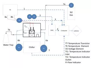
Boundary conditions / assumptions: • Extraction: velocity ~5m/s, area 1,7m2 (velocity inlets) • Inlets: TR1: 3,0m X 3,4 m; TR2: 1,2m X 2,0m (pressure inlets), central – velocity inlet 1,3m X 0,55m • Tunnel leak tight 2013-02-12
Results 2013-02-12
Conventions + + + + • “r45” means flow rate in the tunnel between the technical room 4 and 5. • Flow rate in tunnels (r12, r23, etc.) is positive when counter-clockwise. • Flow rate in galleries is positive when moving radially from the ring center to the outside. 2013-02-12
Velocity in the tunnel (m/s) With air injection in the center Normal 0.05 0.07 0.56 0.43 0.85 0.99 0.38 0.35 0.43 0.79 0.7 0.76 0.68 0.76 1.38 1.19 0.74 0.87 3.96 3.43 1.3 1.14 0.27 0.23 2013-02-12
Air flow rates in the tunnel 2013-02-12
Air flow rates in the galleries • Even galleries have smaller cross section • The flow rate values are taken in the center of the gallery (50 meter from the center of the ring) 2013-02-12
Velocity in the galleries 2013-02-12
Path lines With air injection in the center Normal 2013-02-12
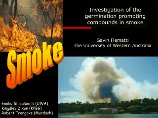
Model of the fire • Fire will be modelled as an mass inflow • No combustion process in the simulation • Power of the fire - 5MW Reaction (in normal conditions): Volume of the smoke: Volumetric flow rate: 2013-02-12
Conclusions Conclusions and suggestions: • Central inlet reduces air going from the ring to the galleries • More flow in the center will improve the results • Flushing of smoke will be the worst in r56 due to very low flow rate • Openings can significantly change the results – they should be taken into account • Efficiency of smoke extraction depends on the position of the fire • Smoke modelled as inlfow (with volumetric flow rate) may change the results • With air injection in the center, less air is taken from two main inlets To be discussed: • Position and size of the fire • Openings – size and position • Increasing the flow in the central room 2013-02-12
END 2013-02-12