Download
1 / 37
370 likes | 537 Views
ALICE Energy Recovery Linac Prototype : Current Status and Commissioning Successes. Lee Jones Accelerator Physics Group ASTeC STFC Daresbury Laboratory. ALICE ERL Prototype status update: Content. Introduction Project status Ongoing work

E N D
ALICE Energy Recovery Linac Prototype:Current Status andCommissioning Successes Lee Jones Accelerator Physics Group ASTeC STFC Daresbury Laboratory
ALICE ERL Prototype status update: Content • Introduction • Project status • Ongoing work • Photon science on the ALICE (formerly known as ERLP) • The EMMA NS-FFAG project • Injector commissioning results • Future plans
ALICE ERL Prototype: Technical priorities Primary Goals: Foremost: Demonstrate energy recovery Produce and maintain bright electron bunches from a photoinjector Operate a superconducting Linac Produce short electron bunches from a compressor Further Development Goals: Demonstrate energy recovery during FEL operation (with an insertion device that significantly disrupts the electron beam) Develop a FEL activity programme which is suitable to investigate the expected synchronisation challenges and demands of 4GLS/NLS Produce simultaneous photon pulses from a laser and an ERL photon source which are synchronised at or below the 1ps level
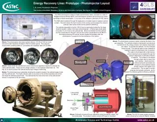
ALICE ERL Prototype: Layout • Nominal gun energy 350 keV • Injector energy 8.35 MeV • Circulating beam energy 35 MeV • Linac RF frequency 1.3 GHz • Bunch repetition rate 81.25 MHz • Max bunch charge 80 pC • Bunch train 100 ms • Maximum average current 13 µA
Construction status • Photoinjector laser system operating since April 2006 • Gun installed and commissioned into a dedicated diagnostic beamline over a period of several months during three commissioning phases • Accel superconducting modules undergoing commissioning • Cryogenic system installed by Linde and DeMaco, and used to cool accelerating modules down to 1.8 K • All of the electron beam transport system has been installed and is under vacuum • Installation work proceeding for various photon beam transport systems
Drive laser: Summary • Diode-pumped Nd:YVO4 • Wavelength: 1064 nm, doubled to 532 nm • Pulse repetition rate: 81.25 MHz • Pulse duration: 7, 13, 28 ps FWHM • Pulse energy: up to 45 nJ (at cathode) • Macrobunch duration: 100 ms @ 20 Hz • Duty cycle: 0.2% (maximum) • Timing jitter: <1 ps (specified) <650 fs (measured) • Spatial profile: Circular top-hat on photocathode • Laser system commissioned at Rutherford Lab in 2005, then moved to Daresbury in 2006 L.B. Jones, Status of the ERLP Photoinjector driver laser, ERL ’07 proceedings
Gun Assembly • JLab design Cs:GaAs cathode • 500 kV DC supply • Single bulk-doped ceramic,manufactured by WESGO Cathode ball Ceramic Cathode SF6 Vessel removed Electrons Laser XHV Support Stem • Power supply commissioned 2005 • Ceramic delivery March 2006 • Spare ceramic delivered Nov 2006 Anode Plate
Gun Commissioning Status • Electron gun operated Jul-Aug ‘06, Jan-Apr ‘07 & Oct-Nov ‘07 • Problems experienced with cathode activation. Q.E. poor • First beam from the gun recorded at 01:08 on Wednesday 16th August 2006, with the gun operating at 250kV • Operating at 350kV soon afterwards • Routinely conditioning gun to 450 kV • Steady improvement in both Q.E. & lifetime • Problems encountered with beam halo, field emission and high voltage breakdown • Improved bakeout º Better vacuum • Repeated failure of ceramic, now using Stanford spare
Design criteria demonstrated so far …… • Beam energy: 350keV ü • Bunch charge: > 80pC ü • Quantum Efficiency (Q.E.):3.7%with 1/e lifetime of ~100 hoursü • Bunch train length: Single 7ps pulse to 100µsü • Train repetition rate: Operated up to 20Hzü
Cryosystem & accelerating modules 2006 Apr – 1st Accelerating module delivered May - 4K cryo commissioning carried out Jul – 2nd Accelerating module delivered Oct - Linac cooled to 2K Nov – Booster cooled to 2K Dec - Modules cooled together • Simulated a dynamic resistive heat load of ~112W in both modules • Achieved a pressure stability of±0.03mbar at full (simulated) dynamic load in both of the modules at 2K • Achieved ±0.10mbar at 1.8K
ScRF Accelerating modules • Main Linac module: • 13.5 MV/m gradient • 16 kW RF power • Quality factor, Q0 ~ 5 × 10⁹ • Total cryogenic load: ~ 180W at 2K • 2 × Stanford/Rossendorf cryomodules, one configured as the Boosterand the other as the MainLinac, also using the JLab HOM coupler • 2× 9-Cell 1.3GHz cavities per module • Booster module: • 4 MV/m gradient • 52 kW RF power
ScRF Accelerating modules • Main Linac module: • 13.5 MV/m gradient • 16 kW RF power • Quality factor, Q0 ~ 5 × 10⁹ • Total cryogenic load: ~ 180W at 2K • 2 × Stanford/Rossendorf cryomodules, one configured as the Boosterand the other as the MainLinac, also using the JLab HOM coupler • 2× 9-Cell 1.3GHz cavities per module • Booster module: • 4 MV/m gradient • 52 kW RF power
Electron beam transport system DipoleMagnet Quadrupole Magnet OTR Girder All modules now installed andunder vacuum. Ready for beam ! Corrector Coil and EBPM Assembly IonPump
Current / ongoing work • Preparing for 4th phase of gun commissioning • 1st phase of beam comissioning • RF Conditioning of accelerating modules • Optimising of the cryogenic system with RF present • Commissioning of high-power RF & PLC control systems • Commissioning of electron BTS sub-systems: • Controls / Diagnostics • Beam Loss Monitor • Machine Protection System • Installation of the photon BTS for THz, FEL, EO & CBS
Started Dec 2005 North West Science Fund award of £3m over 3 years ALICE ERLp Photon science: X-rays: Time resolved X-ray diffraction studies probing shock compression of matter on sub-picosecond timescales. 90º focus mirror X-rays Probe Pump IR 180º focus mirror CBSInteractionPoint THz: Ultrahigh intensity, broadband THz radiation to be utilised for the study of live tissues. THz 25TWLaser Laser-SR synergy: Pump-probe expts with table-top laser and SR
Accelerator Hall Laser Room 2.2 mJ, 35 fs at 1 kHz for EO 800 mJ, 100 fs at 10 Hz for CBS Diagnostics Room Courtesy G. Priebe, DL
Compton Back-Scattering Þ X-rays Courtesy J. Boyce, JLab Courtesy DL Engineering Office
High Harmonic Generation Þ UV Courtesy G. Priebe, DL Current [A] energy [eV]
Electro-Optic concept Longitudinal diagnostics: encoding (bunch profile into optical pulse) probe laser bunch to laser diagnostic decoding(optical pulse into profile measurement) Courtesy S. Jamison, DL
Tunable Free-Electron Laser Encoders JLabWiggler (on loan) • FEL Tunability by varying: • electron energy (24-35 MeV range) • undulator gap (12-20 mm range) l = 4-12 mm
EMMA The EMMA Project
EMMA British Accelerator Science and Radiation Oncology Consortium BASROC: • The long-term aim of BASROC is to build a complete hadron therapy facility using Non-Scaling Fixed-Field Alternating Gradient accelerator technology (NS-FFAG), combining the best features of cyclotron and synchrotron accelerators • An FFAG combines the intensity and ease-of-use of cyclotrons ....... coupled with the benefits of synchrotrons, specifically beam control and the ability to accelerate proton and heavy ion beams to various energies • EMMA: The Electron Model of Many Applications will use ALICE as an injector at 10MeV, accelerating electrons to 20MeV. The goal is to learn how to design NS-FFAGs for various applications, including hadron therapy • PAMELA: The Particle Accelerator for MEdicaLApplications will be a 70-100 MeV proton NS-FFAG, itself a prototype to demonstrate the potential use of NS-FFAGs in hadron therapy, thus strengthening the case for hadron therapy • Leading to acomplete facilityfor the treatment of patients using hadron beams Awarded £6.9m over 3½ years to design and build EMMA
EMMA EMMA on the ALICE ERL
ALICE Gun diagnostic beamline • transverse RMS emittance measured by double-slit scans at positions ‘A’ and ‘B’ • bunch length with slit ‘A’ and kicker cavity Courtesy Y. Saveliev, DL
RMS Geometric emittance (function of bunch charge) • RMS geometric emittance as a function of bunch charge: • - Horizontal ( ) • - Vertical ( ) • ALICE ERLp target was specified as 1·p mm-mrad by ASTRA for Q = 80 pC • Some factors are missing from the ASTRA model1,2 1 I.V. Bazarov et al., Proceedings of PAC’07, Albuquerque, 2007, pp. 1221-1223. 2F. Zhou et al., Phys. Rev. ST - AB 5, 094203, 2003.
Bunch length (function of bunch charge, at 10% level) Bunch length at 10% of the peak value used due to non-uniformity of the longitudinal profile. Data were obtained with the RF transverse kicker (full circles), “energy mapping method” (square) and zero-crossing method (triangle). Open circles are the results from the ASTRA model.
FWHM Beam size for Q = 54 pC B1, G B2, G Second solenoid First solenoid Comparison of predicted and measured beam sizes [mm]as a function of solenoid field strength [guass] for Q = 54 pC
PI Gun driven by differing laser pulse durations ASTRA Longitudinal phase space predictions
PI Gun driven by differing laser pulse durations Longitudinal drive laser profile
PI Gun driven by differing laser pulse durations Conclusion: Longer laser pulses do not confer significant benefits below ~ 20 pC when compared to short pulses in terms of bunch length & energy spectra.
Immediate / future plans Immediate: • Beam through the booster, main linac and arcs • Demonstrate energy recovery Followed by: • Fine tuning of the machine: tune injector for minimum emittance, optimisation of energy recovery at nominal beam parameters, extensive beam measurements • Short pulse commissioning: longitudinal dynamics, EO diagnostics • Energy recovery with FEL and first IR light from the FEL Simultaneously: • THz & IR-FEL research programmes will start, as will CBS X-ray production using head-on electron-photon collisions Future: • Load-lock gun upgrade and possible re-design for vertical ceramic • Re-installation of gun diagnostic line • Installation of an improved high-current cryomodule
Thank you for listening …… EPAC ’08 Proceedings: Y.M. Saveliev et al., Results from ALICE (ERLP) DC photoinjector gun commissioning, MOPC062, pages 208-210 Y.M. Saveliev et al., Characterisation of electron bunches from ALICE (ERLP) DC photoinjector gun at two different laser pulse lengths, MOPC063, pages 211-213 Linac ’08 proceedings: D.J. Holder on behalf of the ALICE team, First results from the ERL prototype (ALICE) at Daresbury Acknowledgements: K.J. MiddlemanY.M. SavelievD.J. HolderS.P. JamisonS.L. Smith B.L. MilitsynB.D. MuratoriG. PriebeN.R. ThompsonJ.W. McKenzie Questions ?