Download
1 / 37
380 likes | 402 Views
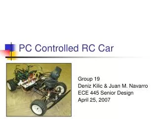
PC Controlled RC Car. Team #12 Sunil Kondala Orbay Tuncay Kyle Zars. Features. Wireless Link (75.870 MHz) from Host Computer to Car On-board Wireless Camera (2.4GHz) with Amplifier for Extended Range User-Friendly Software Control Interface Remote Login Capability. Possible Uses.

E N D
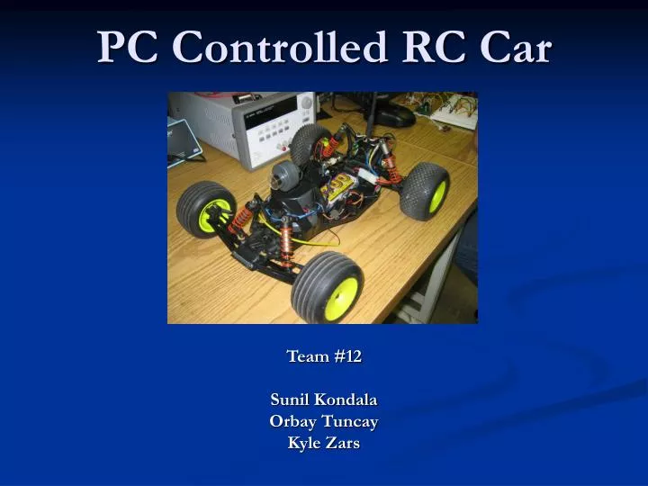
PC Controlled RC Car Team #12 Sunil Kondala Orbay Tuncay Kyle Zars
Features • Wireless Link (75.870 MHz) from Host Computer to Car • On-board Wireless Camera (2.4GHz) with Amplifier for Extended Range • User-Friendly Software Control Interface • Remote Login Capability
Possible Uses • Visual security for entire home with one unit • Maneuver and see into small spaces • Espionage missions • Can also be implemented on an RC boat, plane or helicopter
Objectives/Goals • Make Car Operational Up to 100 ft. (With No Obstacles) • Success – Also Operates Up to 58 ft. Through Two Brick Walls • Delay Between Video Frames on Remote Computer Less than 500 ms. • Success • Delay Less than 100 ms for LAN Connection (MS Remote Desktop)
Design Overview Host PC Remote Control Circuitry/Transmitter Breakout Board Digital Potentiometers Receiver Remote PC Amplifier Camera Receiver/Car
Used for RC Cars, Boats, Airplanes Operates at: 12V, 150mA Utilizes Amplitude Modulation (AM) 26.995MHz to 75.990MHz Channel BW=10kHz Operates at 75.870MHz Channel: 84 XR2i Remote Control
Interior Components • Mechanical Potentiometers • Microprocessor • RF transmitter board • Telescopic Antenna
This potentiometer sweeps through resistances from as low as 60 Ω to as high as 5 kΩ W-> (pin 18 and pin 15) Varies Voltage from 0.8V to 3.8V Potentiometer Mechanical Potentiometer
Microprocessor • Pin 18 (throttle) -> Pin 43 of microprocessor Pin 15 (steering) -> Pin 42 of microprocessor • The ADC in the microprocessor
Digital Potentiometers • 10 KΩ potentiometer • Operates from 2.7V to 5.5V • Current through wiper = 0.12μA Maxim DS1866
Digital Potentiometers • PIN DESCRIPTION H – High End terminal L – Low End terminal W – Wiper Arm P0 – LSB data input P1 – Bit 1 data input P2 – MSB data input Pin 4 – Ground Pin 8 - VCC
Software Interface Design • Buttons vs. Scrollbars or Keyboard • Parts Decision • Digital Potentiometers – Maxim Part #DS1866 • 3 Parallel Inputs (data bus on parallel port is 8 bits) • Operates at 5V (same as parallel port signal voltage) • Output Current Same as Mechanical Pots (~1-2 µA) • 10 kΩ Variable Resistance Range • Parallel Cable Breakout Board • Cost • Easy Terminal Strip/Screw Interface
Software Algorithm Overview • Click on Button – takes you to function • #define Data 0x378 • int Bits; • Conditional Statements on Bits • Holds one channel constant while changing the other • Set Bits to new value • _outp(Data,Bits)
Issues Accessing Parallel Port • Windows XP does not allow access by default • Found UserPort software (shareware) • Configures the Behavior of the Driver
Video Transmitting Software • Clipstream Live (shareware) • Compresses Video to Transmit Over IE • Also Conveniently Compresses Enough For MS Remote Desktop
Capture Card • ATI TV Wonder Card • Receives Coax Input From Wireless Camera Receiver • Clipstream Software Uses this Card for Input of Video Signal
X-10 2.4GHz Wireless Camera Operates w/12V DC, 80mA Resolution : 310 TV lines RF Output of 50,000uV/m @3m FM modulation Receiver operates at 4 channels 2.411GHz to 2.473GHz Channel BW is 18MHz Transmission Range 100ft ANS-900 2.4GHz Monopole 50Ω input impedance 2.5dbi omni-directional gain 1.5:1 VSWR max 10W max input power What we have?
How much amplification do we need? Amplification= Free Space Loss + Path Loss Friis Transmission Formula: PR = PT DT DRλ2 16 π2 d2 PR=Power received by receiving antenna PT=Power radiated by transmitting antenna DT = Directivity of the transmitting antenna DR = Directivity of the receiving antenna λ = Wave length d = Separation between antennas
Free Space Loss: Using Friis Transmission Formula: • Since PT DT DRλ in Friis Formula doesn’t change for different separations, power received is inversely proportional to separation squared: Power Ratio = PR(55ft) = (100ft)2 PR(100ft) (55ft)2 Free Space Loss = 10 log (Power Ratio) [dB] = 5.193dB
Path loss can be estimated as 5dB/wall Typical 2 bedroom apartment has 3 walls Path Loss: http://www.genisysnetworks.com http://www.imperialsouth.com/2bedroomfloorplan.html Path Loss = 5dB/wall * 3 walls = 15 dB Amplification needed = 20.193 dB
X10 transmitter output Spectrum of video signal (20MHz BW) Power spectrum of the transmitter output Output power of the transmitter at 2.411GHz (channel A) = 3.883dBm
Specifications of final power amp: Operate at 2.4GHz ISM band ≈21dB gain High efficiency i.e. low voltage operation Low input power i.e. 4dBm Max output power of 1W≈30dBm (limited by FCC) Impedance matched to 50Ω Desired power amp RF2163 1800MHz to 2500MH operation range Operation voltage 3.3V 19dB gain w/Pin=10dBm +30dBm saturated output power Impedance matched to 50 Ω w/impedance matching network Amplification at the output of transmitter
Output power of transmitter w/MAR8 and 10dB attenuator GMAR8(2.4GHz) = = Pout + 10dB – PTx = 3.47dBm + 10dB – 3.883dBm = 9.587dB OR Wireless camera range of 100ft in free space and ≈1 dry wall BW doesn’t change information is preserved therefore can be substituted for RF2163 Using what we have: MAR8
Overview of MAR8 Vcc = 12V, I = 40mA Powered by RS51-0124 battery
Characterization of MAR8: Input/Output Missmatch • Matched to 50Ω at the input: |S11|< -15dB 2.32GHz < f < 2.48GHz • Matched to 50Ω at the output: |S22|<-15dB 2.33GHz < f < 2.45GHz
Characterization: Stability • Unconditional Stability Criteria are satisfied: • K > 1 2.22GHz < f < 2.60GHz • B1 > 0 0 < f < 2.60GHz
|S21|=12dB f = 2.40GHz Measured gain=9.5dB Since we are operating at power levels 4 dBm, cable losses are significant and effect the measured gain. Characterization: Gain
Challenges/Problems • Operation of Potentiometers • Trouble Figuring Out Correct Configuration • Added 1 kΩ Resistors in Series Between Parallel Port and Input Pins • Amplifier • Was Not Feasible to Build One Given the Time Constraint • Non-Functional Substitutes • Initialization of RF Signals Being Transmitted When Car Is Powered on
Thanks To: • Professor Swenson • Derek Gottlieb • Professor Steven J. Franke • Professor Alex Cangellaris • Chad Carlson • Josh Potts