Download
1 / 20
200 likes | 212 Views
AC, DC or AC+DC voltages above +/-30 volts peak value are potentially a risk This is the case because current can flow through an internal path in the human body that includes the heart and or the chest muscles that control breathing.

E N D
AC, DC or AC+DC voltages above +/-30 volts peak value are potentially a risk • This is the case because current can flow through an internal path in the human body that includes the heart and or the chest muscles that control breathing. • Usually, the overall circuit includes unpredictable parallel paths on the skin that reduce the risk. • Series resistance is often high at the finger tips and feet which limits current.
Externally Measured Current(30 micro-amps in the heart is lethal) • More than 3 ma • painful shock • More than 10 ma • muscle contraction “no-let-go” danger • More than 30 ma • lung paralysis- usually temporary • More than 50 ma • possible ventricular fib. (heart dysfunction, usually fatal) • 100 ma to 4 amps • certain ventricular fibrillation, fatal • Over 4 amps • heart paralysis; severe burns. Usually caused by >600 volts
The most likely source of exposure in the lab environment is to line power at plugs, receptacles and inside equipment. • Typical line voltage values are 120, 208 and 240 VAC. • DC power sources range from 5 VDC to over 1000 VDC. (This is a subject for another lecture.)
Most Common Factors in Electrical Shock Accidents • User is careless or circumvents safety devices and makes physical contact with high voltage. • User creates unsafe condition that is not immediately obvious, such as a shock hazard or thermal run-away condition.
Single Phase AC Waveform 170 V Nominally, a sinusoid with an effective value of 120 VAC. 60 Hz rate (50 Hz) -170 V Electrical components must withstand the peak voltage!DC to AC converters do not produce sinusoidal output unless specified clearly to have this capability.
Power cubes and inexpensive electronic devices 5 A maximum These plugs must be backed up by adequatewire in the wall! If neutral to ground voltageis not near zero, there is a fault.
An auto-transformer has only one winding. There is a common point between the primary and secondary circuits. The auto-transformer can step voltages up or down. The secondary tap may be continuously adjustable.
A two winding transformer provides full AC isolationbetween its primary and secondary windings The primary and secondary circuits are coupled only via the magnetic loop in the transformer core. DC voltage differences can be isolated or different ground references can be achieved
Older buildings on campusor for cost savings Not compatible with120 VAC sockets Newer buildings on campus
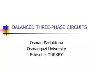
Originally implemented to accommodate motors. Now this is the source for all high power devices and systems (much higher current capacity). 60 Hz 208 or 240 VAC Three overlapping sinusoids, each phase shifted by 120 degrees
3-Phase Delta Configuration In the older buildings on campus. 240 VAC phase to phase.
3-Phase Whye Configuration In the more modern buildings 208 VAC phase to phase 110 VAC phase to neutral
Grounding in Delta System Center grounding on campus. 120 VAC from that phase to ground (maybe). 120 V to gnd 120 V to gnd
No defined ground!Must be adjusteddownward for modernequipment. Cannot necessarilycreated 120 VAC circuits with the same ground Defined ground!Can generate andreference 110 VAC circuits.
2-wire connection May or may not fail-safe. Proper 3-wire connection Fail-Safe because fuse is forced to blow.
The return lead heatsuntil thermal run-away occurs. There will be a slowfire! 400 watts is dissipatedin the lead. 3-wire connection plus long extensioncord. If fuse blows, the lineis disconnected! Fail-safe If fuse blows, the lineis not disconnected! If neutral fuse blows, theline is not disconnected
Electrical Arc Hazards • Mechanical contacts form plasma arc during an opening or closing operation • Contact arc acts as an ignition point for flammable solvents in air. • The hazard is commonly found in refrigeration temperature control circuits
Arc Suppression via Power Distribution System MOV suppressorson transformer windings. MOV suppressors onAC power line and ground