Download
1 / 47
560 likes | 965 Views
Designs with moving parts. BADI 1 John Errington MSc. Axes and degrees of freedom. A rigid object in free space can move in six different ways: Rotation about x, y, z axes Translation about x, y z axes We say it has six degrees of freedom. Joints: movable and fixed.

E N D
Designs with moving parts BADI 1 John Errington MSc
Axes and degrees of freedom A rigid object in free space can move in six different ways: Rotation about x, y, z axes Translation about x, y z axes We say it has six degrees of freedom.
Joints: movable and fixed • Joints are ways of fastening pieces together • Fixed joints prevent any movement between the parts: This picture shows a dovetail joint used in woodwork • Movable joints allow some movement but restrict the degrees of freedom: this picture shows a rose joint used in the suspension of racing cars.
1 degree of freedom: rotation Finger joints also elbow and knee joints allow only one degree of freedom This kind of joint is like a hinge as used on cupboards and doors
2 degrees of freedom The hip joint allows two degrees of freedom: • Forwards-backwards • Inwards-outwards
4 degrees of freedom • The spine is made up of bones (vertebrae) separated by pads (disks) • The joints of the spine allow movement but only within a very restricted range at each joint • Stretching • Bending sideways • Bending forwards • Turning • Lateral translation (sideways and forward/back) are not allowed.
Sliding mechanisms Door bolts are good examples of the case where one part slides inside another. 1DOF The toolpost on a lathe must have its position very closely controlled. A wedge shaped slide arrangement provides this control and can be adjusted to take up wear.
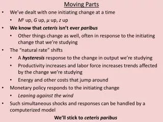
Designs with moving parts • Many designs such as these electric drills feature moving parts. • A shaft can move in any of three different directions (up-down, front- back, left-right) and can rotate in three different directions. It has six degrees of freedom. • Practical applications usually require the removal of some of these alternatives, so that in the drill we leave only the freedom to rotate about the chuck axis.
y z x Rigid body (motor) has six degrees of freedom Drill must have only 1 degree of freedom: axial rotation forward or reverse about the x axis In use pressing the drill bit against the workpiece causes a reaction pressing the moving parts to the back of the casing. y y Controlling the shaft as shown here will prevent: Translation up/down, sideways or front/back Rotation about y and z axes Front view Rear view z z
How to restrict movement • Controlling these movements requires us to hold the shaft in some way. However • When two surfaces rub together the friction between them causes heat and wear. • So we need devices that will constrain the motion and yet minimise friction to give a reliable product.
Friction Friction is a force that tends to oppose the relative motion of two surfaces in contact with each other The work done in overcoming friction results in noise, heat and wear of moving parts
What causes friction? • Friction occurs in part because rough surfaces tend to catch on one another as they slide past each other. Even surfaces that are apparently smooth can be rough at the microscopic level. They have many ridges and grooves. The ridges of each surface can get stuck in the grooves of the other, effectively creating a type of mechanical bond, or glue, between the surfaces. • Smooth surfaces in contact also tend to attract one another at the molecular level, forming chemical bonds. These bonds can prevent an object from moving, even when it is pushed. If an object is in motion, these bonds form and release. Making and breaking the bonds takes energy away from the motion of the object.
Factors affecting the friction between surfaces • Are the surfaces smooth • Clean • Wet or dry • Lubricated or dry • Lubricants provide a protective film that separates the two rubbing surfaces and reduces the level of friction in the two rubbing surfaces. • Surface temperatures
Dry surfaces • For low surface pressures the friction is directly proportional to the pressure between the surfaces. As the pressure rises the friction factor rises slightly. At very high pressure the friction factor then quickly increases to seizing • For low surface pressures the coefficient of friction is independent of surface area. • At low velocities the friction is independent of the relative surface velocity. At higher velocities the coefficient of friction decreases.
Well lubricated surfaces • The friction resistance is almost independent of the specific pressure between the surfaces. • At low pressures the friction varies directly as the relative surface speed. • At high pressures the friction is high at low velocities falling as the velocity increases to a minimum at about 0.6m/s. The friction then rises in proportion to the square of the velocity. • The friction is not so dependent of the surface materials. • The friction is related to the temperature as this affects the viscosity of the lubricant
How Lubricants Work Any surface contains irregularities, even when polished to a mirror finish. These irregularities may not be visible, except under a microscope. When two surfaces are brought gently together, only some points on the surfaces will make contact. These contacts will be brought closer together when a force is applied at right angles to the surfaces (this force is referred to as a ‘normal load’), and the number of contact points will increase.
Lubricated surfaces If a protective film were present on each of the surfaces, the surfaces would be separated. The protective film must adhere to each surface in order not to be sheared off or pushed aside by the movement of the surfaces, particularly under a load.
Bearings Bearings provide either a sliding or a rolling contact whenever relative motion exists between parts of a machine. Sliding contact bearings are referred to as plain bearings and rolling contact bearings are often called antifriction bearings. Bearings that provide sliding contact fall into three general classes: • radial bearings that support rotating shafts; • thrust bearings that support axial loads on rotating shafts; and • linear bearings that guide moving parts in a straight line.
Bearings keep shafts in place • Here tapered roller bearings keep the car wheel in place while allowing it to rotate. • The bearings are subject to both axial (thrust) load and radial load
Plain bearings A common plain bearing design is to use a hardened and polished steel shaft and a soft bronze bushing. In such designs the softer bronze portion can be allowed to wear away, to be periodically renewed. Plain 'self-lubricating' bearings utilize porous journals within which a lubricant is held. As the bearing operates and lubricant is displaced from the bearing surface, more is carried in from non-wear parts of the bearing.
Dry plain bearings Dry plain bearings can be made of a variety of materials including PTFE (Teflon) or ceramic. The ceramic is very hard, and sand and other grit which enter the bearing are simply ground to a fine powder which does not inhibit the operation of the bearing. PTFE has a very low coefficient of friction and acts as a lubricant – but it isn’t very hard so is often just used as a coating on the inside surfaces
Plain Bearings • A steel insert with babbitt (lead alloy) bonded to the bearing surface • Plain bearings are keyed to keep them in place • A lip or flange allows the plain bearing to accept thrust loads • Commonly used as crankshaft and rod bearings in car engines
Lubrication of plain bearings The relative motions between the mating surfaces of a plain bearing may take place in the following ways: 1. Pure sliding without any lubricating medium between the moving surfaces.2. Hydrodynamic lubrication where a film buildup of lubricating medium is produced by the relative motion of the components.3. Hydrostatic lubrication where a lubricating medium is introduced under pressure between the moving surfaces.4. A combination of hydrodynamic and hydrostatic lubrication.
Anti friction bearings Ball roller Thrust tapered roller
Antifriction bearings Antifriction bearings minimize friction by removing any possible sliding between bearing surfaces and replacing all contacts with rolling interfaces. They substitute balls or rollers for a hydrodynamic or hydrostatic fluid film to carry loads with reduced friction. They utilize a separator to space the hardened rolling elements apart. The Anti-Friction Bearing Manufacturers Association Standards (AFBMA) provides standardized dimensions, tolerances and fits of ball and roller bearings so replacement is easy.
advantages and disadvantages of plain bearings vs antifriction bearings.
Rolling Friction When a cylinder rolls on a surface the force resisting motion is termed rolling friction. Rolling friction is generally considerably less than sliding friction. If W is the force between the rolling cylinder and the stationary surface, R is the radius of the cylinder and F is the force required to overcome the rolling friction, then F = fr x W / R fr is the coefficient of rolling friction and has the same unit of length as the radius R.
Typical values for rolling friction Note: Values for rolling friction from various sources are not consistent and these values should only be used for approximate calculations. Remember also the coefficient of rolling friction is dependent on the cylinder radius and therefore has units of length (metres).
Types of antifriction bearing The types of antifriction bearing are grouped by the shape of the rolling element and they are: • ball bearings. • cylindrical roller bearings. • tapered roller bearings. and • needle roller bearings.
Single-Row Ball Bearing. Non-Filling Slot This type of ball bearing is also known as the Conrad or Deep-groove type. It is a symmetrical unit capable of taking combined radial and thrust loads. These bearings are not self-aligning therefore accurate alignment between shaft and housing bore is required.
Parts of a Ball Bearing BALL CAGE INNER RACE OUTER RACE
Mostly used for radial loads • Thrust loads need deep grooves in races • Excessive thrust load causes wear and deformation of races and balls
Roller Bearings (antifriction) • Hard steel rollers held between an inner and outer “race” and held in alignment by a “cage” • May be tapered to absorb radial and thrust loads or straight to absorb radial loads only
Cylindrical Roller These bearings have solid or helically wound hollow cylindrical rollers. The free ring may have a restraining flange to provide some restraint to endwise movement in one direction or maybe without a flange so that the bearing rings may be displaced axially with respect to each other.
Tapered Roller Tapered roller bearings are a variation on the cylindrical rollers. They are held in accurate alignment by a guide flange on the inner ring. The shape of the roller is tapered rather than straight right cylindrical. This allows thrust loads to be withstood in addition to the radial loads.
Needle Roller Needle bearings are characterized by their relatively small size rollers. The diameter of needle roller is usually less than ¼" in diameter. The length of needle roller can range from 3 to 10 times its diameter. The loose-roller is the most widely used needle roller and it has no integral races. The needle rollers are located directly between the shaft and the outer bearing bore. This type of bearing is capable of high radial load capacity.
Thrust bearings • Used to provide lateral stabilisation to a rotating shaft • Susceptible to damage if axial load is exceeded • Often used in conjunction with a ball or roller bearing to control the axial load
PTFE • PTFE is widely used as an additive in lubricating oils and greases. Due to the low surface energy of PTFE, stable unflocculated dispersions of PTFE in oil or water can be produced. Contrary to the other solid lubricants discussed, PTFE does not have a layered structure. The macro molecules of PTFE slip easily along each other, similar to lamellar structures. PTFE shows one of the smallest coefficients of static and dynamic friction, down to 0.04. Operating temperatures are limited to about 260ºC.
Plain lubricated bearings Plain bearings can be classified into two types: hydrodynamic bearings and hydrostatic bearings. • Hydrodynamic bearings create lift between the mating surfaces by wedging lubricant into the contact area with a relatively high rotational speed. The disadvantage of this design is the lack of lubricant on the surfaces when the shaft begins to rotate. Thus machineries that utilize this type of bearings should not be subjected to a high load during startup. • Hydrostatic bearings utilize an external source to force lubricant into the contact. They are used in heavily loaded and slow moving machines where the rotation speed is not great enough to form full film lubrication.
Tin-Lead & Tin-Copper Alloys (white metal bearings) • Tin-Lead & Tin-Copper alloys have good characteristics for bearings. Most importantly for bearings, the material should be hard and wear resistant and have a low coefficient of friction. It must also be shock resistant. tough and sufficiently ductile to allow for slight misalignment prior to running in. • These alloys consist of small particles of a hard compound embedded in the tough ductile background of a solid solution. In service the latter can wear away slightly leaving the hard compound to carry the load. This wear also provides channels to allow in lubricant (oils). All bearing metals contain Antimony (Sb) which creates hard cubic crystals.
Circumferential Groove Bearings This type of bearing has an oil groove extending circumferentially around the bearing. The oil is maintained under pressure in the groove. The groove divides the bearing into two shorter bearings that tend to run at a slightly greater eccentricity. This design is most commonly used in reciprocating load main and connecting rod bearings because of the uniformity of oil distribution.
Pressure Bearings Pressure bearings employ a groove over the top half of the bearing. The groove terminates at a sharp dam about 45° beyond the vertical in the direction of shaft rotation. Oil is pumped into this groove by shear action from the rotation of the shaft and is then stopped by the dam. In high speed operating. this situation creates a high oil pressure over the upper half of the bearing. The pressure created in the oil groove and surrounding upper half of the bearing increases the load on the lower half of the bearing. This self-generated load increases the shaft eccentricity. Stability under high speed and low-load condition can be attained if the eccentricity is increased to 0.6 or greater. The primary disadvantage of this design is dirt in the oil will tend to smooth out the sharp edge of the dam and impair the effectiveness to create high pressures.
Multiple Groove Bearings Multiple groove bearings are sometimes used to provide increased oil flow. The interruptions in oil flow film also appear to give this bearing some merit as a stable design.
Hydrostatic Bearings Hydrostatic bearings are used when operating conditions require full film lubrication that cannot be developed hydro-dynamically. The hydrostatically lubricated bearing is supplied with lubricant under pressure from an external source. Advantages of the hydrostatic bearing over bearings of other type are lower friction, higher load capacity, higher reliability, and longer life.
Antifriction Bearings Antifriction bearings include ball and roller bearings. They are more desirable than plain bearings due to their lower friction and reduced lubrication requirement. However the life of an antifriction bearing is limited by the fatigue life of the material they are made of and the type of lubricant being used.