Download
1 / 19
210 likes | 447 Views
NORTH DAKOTA STATE UNIVERSITY. A Conformal CPW Folded Slot Antenna Array Printed on a Kapton Substrate. Masud A. Aziz Sayan Roy * Layne A. Berge Irfanullah Sanjay Nariyal Benjamin D. Braaten. Department of Electrical and Computer Engineering North Dakota State University Fargo, ND, USA.

E N D
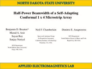
NORTH DAKOTA STATE UNIVERSITY A Conformal CPW Folded Slot Antenna Array Printed on a Kapton Substrate Masud A. AzizSayan Roy*Layne A. BergeIrfanullahSanjay NariyalBenjamin D. Braaten Department of Electrical and Computer EngineeringNorth Dakota State UniversityFargo, ND, USA APPLIED ELECTROMAGNETICS LAB
NORTH DAKOTA STATE UNIVERSITY Topics • 1) Introduction and Background • 2) Conformal CPW Folded Slot Array • 3) Measurement and Simulation Results • 4) Proposed Design Guidelines • 5) Conclusion APPLIED ELECTROMAGNETICS LAB
NORTH DAKOTA STATE UNIVERSITY Introduction and Background Schematic of the CPW (Co Planar Waveguide) –fed single folded slot antenna [1]: [1] D. E. Anagnostou and A. A. Gheethan, “A coplanar reconfigurable folded slot antenna without bias network for WLAN applications,”, IEEE Antennas And Wireless Propagation Letters, vol. 8, pp. 1057-1060, Sep. 2009. APPLIED ELECTROMAGNETICS LAB
NORTH DAKOTA STATE UNIVERSITY Conformal CPW Folded Slot Array b = 5.00 mm, s = 61.00 mm, ws= 21.37 mm, Ls= 43.40 mm, r = 41.80 mm, d = 2.00 mm, g = 0.63 mm, m = 1.79 mm, n = 0.71 mm, Lf= 2.77 mm, P = 43.5 mm and Q = 160.5 mm. Substrate Thickness : 0.05 mmDielectric Permittivity: 2.91 APPLIED ELECTROMAGNETICS LAB
NORTH DAKOTA STATE UNIVERSITY Measurement and Simulation Results Printed two-element CPW folded slot antenna array on 2 mil Kapton substrate APPLIED ELECTROMAGNETICS LAB
NORTH DAKOTA STATE UNIVERSITY Measurement and Simulation Results Prototype antenna diagram with a bend angle of ϕb on a conformal surface (wedge) APPLIED ELECTROMAGNETICS LAB
NORTH DAKOTA STATE UNIVERSITY Measurement and Simulation Results • The resonant frequency was measured to be 3.29 GHz with a 10dB bandwidth of 250 MHz for ϕb =0°. • A good impedance match can be observed for each bend angle. • The impedance match of the antenna is essentially independent of ϕb below 45°. APPLIED ELECTROMAGNETICS LAB
NORTH DAKOTA STATE UNIVERSITY The measured and simulated normalized field patterns on aconformal surface with ϕb= 0° in x-z plane in y-z plane APPLIED ELECTROMAGNETICS LAB
NORTH DAKOTA STATE UNIVERSITY Measurement and Simulation Results Prototype antenna diagram with a bend angle of ϕb on a conformal surface (wedge) APPLIED ELECTROMAGNETICS LAB
NORTH DAKOTA STATE UNIVERSITY Comparison of the measured normalized field pattern in the x-z plane on a conformal surface with ϕb= 0° APPLIED ELECTROMAGNETICS LAB
NORTH DAKOTA STATE UNIVERSITY Comparison of the measured normalized field pattern in the x-z plane on a conformal surface with ϕb= 30° APPLIED ELECTROMAGNETICS LAB
NORTH DAKOTA STATE UNIVERSITY Comparison of the measured normalized field pattern in the x-z plane on a conformal surface with ϕb= 45° APPLIED ELECTROMAGNETICS LAB
NORTH DAKOTA STATE UNIVERSITY Measurement and Simulation Results APPLIED ELECTROMAGNETICS LAB
NORTH DAKOTA STATE UNIVERSITY Proposed Design Guidelines b = 5.00 mm, s = 61.00 mm, ws= 21.37 mm, Ls= 43.40 mm, r= 41.80 mm, d = 2.00 mm, g = 0.63 mm, m = 1.79 mm, n = 0.71 mm, Lf= 2.77 mm, P = 43.5 mm and Q = 160.5 mm. Changes in Geometry Changed Parameters: ws , Ls , r , one at a time APPLIED ELECTROMAGNETICS LAB
NORTH DAKOTA STATE UNIVERSITY Proposed Design Guidelines Effect of changes in ws(slot height) Observation:S11 can be improvised by increasing the dimension of the radiating slot of the antenna. Advantage:A better S11 can be obtained without changing the overall dimension of the antenna APPLIED ELECTROMAGNETICS LAB
NORTH DAKOTA STATE UNIVERSITY Proposed Design Guidelines Effect of changes in Ls(slot width) Observation:A second resonance point at 2.3 GHz has been found without any changes of the default characteristics of the antenna Advantage:Dual-band characteristics can be achieved without changing the overall dimension of the antenna APPLIED ELECTROMAGNETICS LAB
NORTH DAKOTA STATE UNIVERSITY Proposed Design Guidelines Effect of changes in r (size of the dipole) Observation:The resonance frequency can be changed by decreasing the size of the dipole exciting the radiating slot of the antenna Advantage:The overall radiating frequency can be decreased without changing the overall dimension of the antenna APPLIED ELECTROMAGNETICS LAB
NORTH DAKOTA STATE UNIVERSITY Conclusion • Introduction and Background on the CPW-fed slot antenna has been discussed. • Conformal CPW-fed slot antenna array has been introduced. • Measurement and Simulation Results are compared for different bend angles of the surface of the antenna. • New design guidelines have been proposed for the improvisation of the antenna characteristics. APPLIED ELECTROMAGNETICS LAB
NORTH DAKOTA STATE UNIVERSITY Questions? Thank you for listening! APPLIED ELECTROMAGNETICS LAB