Download
1 / 10
100 likes | 299 Views
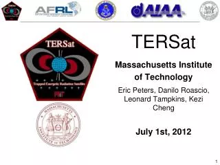
TERSat Massachusetts Institute of Technology Eric Peters, Danilo Roascio, Leonard Tampkins, Kezi Cheng June 29, 2012. Mission Background. Radiation in Earth orbit harms satellites Natural radiation: High energy particles from solar wind are trapped in Van Allen Belts

E N D
TERSat Massachusetts Institute of Technology Eric Peters, Danilo Roascio, Leonard Tampkins, Kezi Cheng June 29, 2012
Mission Background • Radiation in Earth orbit harms satellites • Natural radiation: High energy particles from solar wind are trapped in Van Allen Belts • Man-made: high altitude nuclear activity • Gap in radiation belts is caused by lightning • Can we scatter radiation particles by emitting VLF waves, like lightning? Van Allen Belts SOHO composite image by Steve Hill (NASA) Stanford VLF group image
Mission Overview Satellite Goals: • Demonstrate wave-particle interaction within the inner Van Allen belts • Transmit VLF waves at LEO altitude • Demonstrate science behind potential radiation remediation technique SHOT II Goal: • Use VLF wave transmitter to demonstrate ability to transmit signal to a receiver on the ground Connection: • Demonstrates payload concept of operations, tests prototype VLF receiver parts Example TERSat Interaction with DSX Mini-demo
Payload Design Structure Foam Box • Structure: • Foam box with high impact foam on bottom to mount electronics • Weight: 1.45 kg • Dimensions: 8.5” x 11” x 5” • Mylar for thermal insulation • Balloon attachment cord runs through middle of payload Two antennas: 17 kHz copper coil along perimeter 34 kHz aluminum plates on long sides
Circuit design includes: • Crystal oscillator for frequency stability • Payload Amplifier • Morse code keyer 2 Voltage Data Loggers with peak detector conditioning to evaluate power going into aluminum plates + Payload Design Electronics
Ettus USRP SDR Receiver Low-frequency daughter boards Sampling between 0 and 125 kH Custom Low Noise Amplifier tuned to operate between 1kHz and 80 kHz Attached to square loop antenna Ground Station Design
SHOT Functional Testing Received signal Lot of noise in VLF band Morse Keying helps identify signal Morse code: Hello World Cooling Test First prototype – not insulated enough Second prototype – Thicker foam + Mylar sheet show better thermal insulation
Mechanical Testing Drop Test Whip Test • Successful! • Battery held down • Box maintained shape • Screws were set Drop Test Stair Test