Download
1 / 63
630 likes | 835 Views
Real-time Acquisition and Rendering of Large 3D Models. Szymon Rusinkiewicz. Shape. Rendering. 3D Scanning. Computer Graphics Pipeline. Shape. Human time = expensive Sensors = cheap Computer graphics increasingly relies on measurements of the real world. Motion. Lighting and

E N D
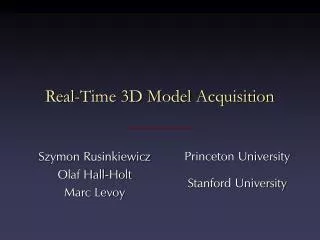
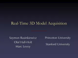
Real-time Acquisition and Rendering of Large 3D Models Szymon Rusinkiewicz
Shape Rendering 3D Scanning Computer Graphics Pipeline Shape • Human time = expensive • Sensors = cheap • Computer graphics increasingly relies onmeasurements of the real world Motion Lighting and Reflectance
Computer graphics Product inspection Robot navigation As-built floorplans Product design Archaeology Clothes fitting Art history 3D Scanning Applications
The Digital Michelangelo Project • Push state of the art in range scanning and demonstrate applications in art and art history Working in the museum Scanning geometry Scanning color
Traditional Range Scanning Pipeline • High-quality, robust pipeline for producing 3D models: • Scan object with laser triangulation scanner: many views from different angles • Align pieces into single coordinate frame:initial manual alignment, refined with ICP • Merge overlapping regions: compute “average” surface using VRIP [Curless & Levoy 96] • Display resulting model
3D Scan of David: Statistics • Over 5 meters tall • 1/4 mm resolution • 22 people • 30 nights of scanning • Efficiency max : min = 8 : 1 • Needed view planning • Weight of gantry: 800 kg • Putting model together:1000+ man-hours and counting
Real-Time Model Acquisition New 3D Scanning Pipeline • Need for a fast, inexpensive,easy-to-use 3D scanning system • Wave a (small, rigid) object by hand in front of the scanner • Automatically align data asit is acquired • Let user see partial model as itis being built – fill holes
Real-Time 3D Model Acquisition • Prototype real-time model acquisition system • 3D scanning of moving objects • Fast alignment • Real-time merging and display
Applications of Easy-to-Use3D Model Acquisition • Advertising • More capabilities in Photoshop • Movie sets • Augmented reality • User interfaces
3D Scanning Technologies • Contact-based: touch probes • Passive: shape from stereo, motion, shading • Active: time-of-flight, defocus, photometric stereo, triangulation • Triangulation systems are inexpensive, robust, and flexible • Take advantage of trends in DLP projectors
Laser Camera Laser Triangulation • Project laser stripe onto object Object
Laser Camera Laser Triangulation • Depth from ray-plane triangulation Object (x,y)
Triangulation • Faster acquisition: project multiple stripes • Correspondence problem: which stripeis which?
Multi-stripe Multi-frame Single-stripe Single-frame Triangulation Slow, robust Fast, fragile
Time-Coded Light Patterns • Assign each stripe a unique illumination codeover time [Posdamer 82] Time Space
Gray-Code Patterns • To minimize effects of quantization error:each point may be a boundary only once Time Space
Structured-Light Assumptions • Structured-light systems make certain assumptions about the scene: • Spatial continuity assumption: • Assume scene is one object • Project a grid, pattern of dots, etc. • Temporal continuity assumption: • Assume scene is static • Assign stripes a code over time
Codes for Moving Scenes • We make a different assumption: • Object may move • Velocity low enough to permit tracking • “Spatio-temporal” continuity
Illumination history = (WB),(BW),(WB) Code Codes for Moving Scenes • Code stripe boundariesinstead of stripes • Perform frame-to-frametracking of correspondingboundaries • Propagate illumination history [Hall-Holt & Rusinkiewicz, ICCV 2001]
New Scanning Pipeline Project Code Capture Images Find Boundaries Match Boundaries Decode Compute Range
Designing a Code • Biggest problem is ghosts – WW or BB “boundaries” that can’t be seen directly Project Code Capture Images Find Boundaries Match Boundaries Decode Compute Range
Designing a Code • Design a code to make tracking possible: • Do not allow two spatially adjacent ghosts • Do not allow two temporally adjacent ghosts t
0000 1101 • Nodes: stripes (over time) 1010 0111 • Edges: boundaries (over time) 1111 0010 0101 1000 1011 0110 0001 1100 0100 1001 Time 1110 0011 Space Designing a Code • Graph (for 4 frames):
Path with alternating colors:55 edges in graph maximal-length traversal has 110 boundaries (111 stripes) 0000 1101 • Nodes: stripes (over time) 1010 0111 1111 0010 0101 1000 Boundary visible at even times Boundary visible at odd times 1011 0110 0001 1100 0100 1001 1110 0011 Designing a Code • Graph (for 4 frames): • Edges: boundaries (over time)
Image Capture • Standard video camera: fields at 60 Hz • Genlock camera to projector Project Code Capture Images Find Boundaries Match Boundaries Decode Compute Range
Finding Boundaries Project Code Capture Images Find Boundaries Match Boundaries Decode Compute Range • Standard edge detection problem • Current solution: find minima and maxima of intensity, boundary is between them
Matching Stripe Boundaries Project Code Capture Images Find Boundaries Match Boundaries Decode Compute Range • Even if number of ghosts isminimized, matching is not easy ?
Matching Stripe Boundaries • Resolve ambiguity by constraining maximum stripe velocity • Could accommodate higher speeds by estimating velocities • Could take advantage of methods intracking literature (e.g., Kalman filters)
Decoding Boundaries Project Code Capture Images Find Boundaries Match Boundaries Decode Compute Range • Propagate illumination history • Table lookup based on illumination history and position in four-frame sequence • Once a stripe has been tracked for at least four frames,it contributes useful data on every subsequent frame
Computing 3D Position • Ray-plane intersection • Requires calibration of: • Camera, projector intrinsics • Relative position and orientation Project Code Capture Images Find Boundaries Match Boundaries Decode Compute Range
Results Video frames Stripe boundaries unknown known ghosts
Results • Single range image of moving object Top View Front View Top View Front View Boundary codes and tracking Gray codes, no tracking
Aligning 3D Data • This range scanner can be used for any moving objects • For rigid objects, range images can be aligned to each other as object moves
Aligning 3D Data • If correct correspondences are known,it is possible to find correct relative rotation/translation
Aligning 3D Data • How to find corresponding points? • Previous systems based on user input,feature matching, surface signatures, etc.
Aligning 3D Data • Alternative: assume closest points correspond to each other, compute the best transform…
Aligning 3D Data • … and iterate to find alignment • Iterated Closest Points (ICP) [Besl & McKay 92] • Converges if starting position “close enough“
ICP Variants • Classic ICP algorithm not real-time • To improve speed: examine stages of ICP and evaluate proposed variants [Rusinkiewicz & Levoy, 3DIM 2001] • Selecting source points (from one or both meshes) • Matching to points in the other mesh • Weighting the correspondences • Rejecting certain (outlier) point pairs • Assigning an error metric to the current transform • Minimizing the error metric
ICP Variant – Point-to-Plane Error Metric • Using point-to-plane distance instead of point-to-point lets flat regions slide along each other more easily [Chen & Medioni 91]
Finding Corresponding Points • Finding closest point is most expensive stage of ICP • Brute force search – O(n) • Spatial data structure (e.g., k-d tree) – O(log n) • Voxel grid – O(1), but large constant, slow preprocessing
Finding Corresponding Points • For range images, simply project point [Blais 95] • Constant-time, fast • Does not require precomputing a spatial data structure
High-Speed ICP Algorithm • ICP algorithm with projection-based correspondences, point-to-plane matchingcan align meshes in a few tens of ms.(cf. over 1 sec. with closest-point)
Anchor Scans • Alignment of consecutive scans leads to accumulation of ICP errors • Alternative: align all scans to an “anchor” scan, only switch anchor when overlap low • Given anchor scans, restart after failed ICP becomes easier
Merging and Rendering • Goal: visualize the model well enoughto be able to see holes • Cannot display all the scanned data – accumulates linearly with time • Standard high-quality merging methods:processing time ~ 1 minute per scan
Merging and Rendering • Real-time incremental merging and rendering: • Quantize samples to a 3D grid • Maintain average normal of all pointsat a grid cell • Point (splat) rendering • Can be made hierarchical to conserve memory
Postprocessing • Goal of real-time display is to let user evaluate coverage, fill holes • Quality/speed tradeoff • Offline postprocessing for high-quality models
Merged Result Photograph Aligned scans Merged
Future Work • Technological improvements: • Use full resolution of projector • Higher-resolution cameras • Ideas from design of single-stripe 3D scanners • Pipeline improvements: • Better detection of failed alignment • Better handling of object texture – combine with stereo? • Global registration to eliminate drift • More sophisticated merging • Improve user interaction during scanning