Download
1 / 19
190 likes | 212 Views
This lecture covers the hardware and software components of fMRI experiments, including coils, amplifiers, electromagnetic radiation, and pulse sequence diagrams.

E N D
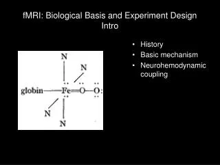
fMRI: Biological Basis and Experiment DesignLecture 6: Pulse Sequences • Hardware • Software www.hoghaven.com
Hardware • Coils • RF • Gradient RF Head coil from www.nmr.mgh.harvard.edu/~rhoge/HST583/doc/HeadCoil.jpg Gradient coil picture from www.med.umn.edu/.../cvs/martin/gallery.html • Amplifiers • RF • Input • Output ("pre-amp") • Gradient
Electromagnetic radiation • Electromagnetic energy (light, RF wave, radiated heat) travels as a pair of oscillating electric and magnetic fields • Polarization is determined by the orientation of the E field ls7pm3.gsfc.nasa.gov/whatsRM/em.html
Parallel Imaging Arrays at 7T 2002 2003 Start: 4 Loop 8 Loop 8 Strip 16 Strip 15 Strip Open 32 Strip 2004
Software SYNGO console - choose pulse sequence - set parameters - ... - image display and storage MR-IR - image reconstruction Can't remember name - final safety checks - send actual commands to hardware
Parts of a pulse sequence • Magnetization preparation: when equilibrium doesn't give you the contrast you want • Important timing parameter: TI = inversion time • Excitation: rotate (prepared) magnetization to transverse plane • Important timing parameter: TR = repetition time • Read-out: detect transverse magnetization • Important timing parameter: TE = echo time
Pulse sequence diagrams Magnetization preparation Excitation Read-out Nrep RF GSS GPE GRO DAC
Magnetization preparation T1-contrast enhanced by inversion preparation No inversion preparation
Inversion recovery (magnetization preparation) An image taken at this point will have white matter brighter than gray matter; no signal from CSF
Inversion recovery (partial volume effects) An image taken at this point will have a black boundary between white / gray and CSF (which won't be black)
Pulse sequence diagram: MP-RAGE (256 x 256) Inversion pulse Nrep = 256 Inversion time Excitation pulse TR ~ 10 ms RF GSS PE table increments each repetition GPE GRO 256 points DAC
Pulse sequence diagram: EPI (128 x 128 image) Inversion pulse TR =2500 ms Nrep = 64 TI = 900ms RF GSS GPE GRO 128 pts 128 pts DAC