Download
1 / 81
870 likes | 1.2k Views
Auto 165 – Automotive Engine Performance. Chapter 16 Ignition System Components and Operation. OBJECTIVES. After studying Chapter 16, the reader will be able to: Prepare for ASE Engine Performance (A8) certification test content area “B” (Ignition System Diagnosis and Repair).

E N D
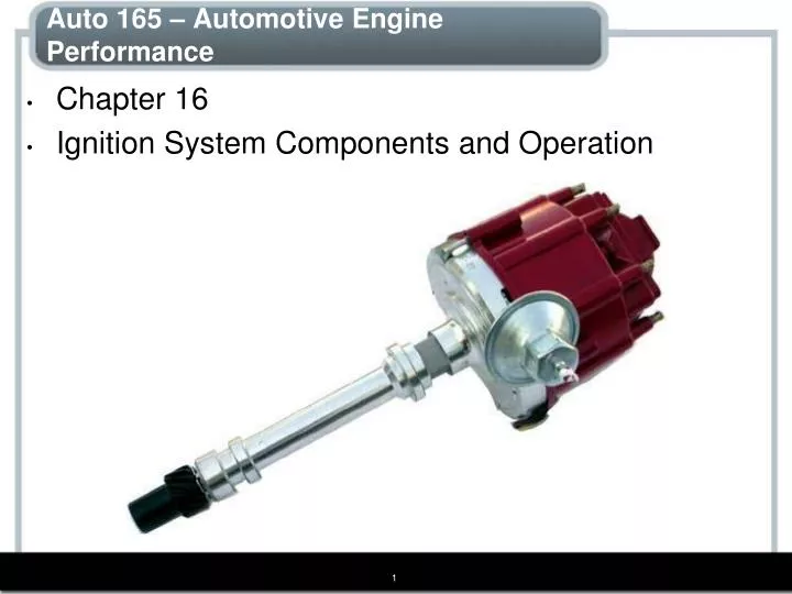
Auto 165 – Automotive Engine Performance • Chapter 16 • Ignition System Components and Operation
OBJECTIVES After studying Chapter 16, the reader will be able to: • Prepare for ASE Engine Performance (A8) certification test content area “B” (Ignition System Diagnosis and Repair). • Explain how ignition coils create 40,000 volts. • Discuss crankshaft position sensor and pickup coil operation. • Describe the operation of waste-spark and coil-on-plug ignition systems.
Electronic ignition system (EIS) Electronic spark timing (EST) Flyback voltage Hall-effect switch High energy ignition (HEI) Igniter Ignition coil Ignition control (IC) Ignition control module (ICM) Ignition timing Inductive reactance Initial timing Ion-sensing ignition Iridium spark plugs Knock sensor (KS) Magnetic pulse generator Magnetic sensor Married coil Mutual induction Optical sensors Paired cylinder Pickup coil (pulse generator) Ping Platinum spark plugs Polarity Primary ignition circuit Saturation Schmitt trigger Secondary ignition circuit Self-induction Spark knock Spark output (SPOUT) Switching Tapped transformer Transistor Trigger True transformer Turns ratio Up-integrated ignition Waste-spark ignition KEY TERMS
IGNITION SYSTEM OPERATION • The ignition system includes components and wiring necessary to create and distribute a high voltage (up to 40,000 volts or more). • All ignition systems apply voltage close to battery voltage (12 volts) to the positive side of the ignition coil and pulse the negative side to ground. • When the coil negative lead is grounded, the primary (low-voltage) circuit of the coil is complete and a magnetic field is created around the coil windings.
IGNITION SYSTEM OPERATION • When the circuit is opened, the magnetic field collapses and induces a high-voltage spark in the secondary winding of the ignition coil. • Early ignition systems used a mechanically opened set of contact points to make and break the electrical connection to ground. • Electronic ignition uses a sensor, such as a pickup coil and reluctor (trigger wheel), or trigger to signal an electronic module that makes and breaks the primary connection of the ignition coil.
IGNITION COILSPURPOSE AND FUNCTION • The heart of any ignition system is the ignition coil. • The coil creates a high-voltage spark by electromagnetic induction. • Many ignition coils contain two separate but electrically connected windings of copper wire. • Other coils are true transformers in which the primary and secondary windings are not electrically connected.
IGNITION COILSPURPOSE AND FUNCTION • Internal construction of an oil-cooled ignition coil. Notice that the primary winding is electrically connected to the secondary winding. The polarity (positive or negative) of a coil is determined by the direction in which the coil is wound.
IGNITION COILSCOIL CONSTRUCTION • The center of an ignition coil contains a core of laminated soft iron (thin strips of soft iron). • This core increases the magnetic strength of the coil. • Surrounding the laminated core are approximately 20,000 turns of fine wire (approximately 42 gauge). • These windings are called the secondary coil windings. • Surrounding the secondary windings are approximately 150 turns of heavy wire (approximately 21 gauge). • These windings are called the primary coil windings.
FIGURE 16–2 Typical air-cooled epoxy-filled E coil. IGNITION COILSCOIL CONSTRUCTION
FIGURE 16–3 IGNITION COILSCOIL CONSTRUCTION • Cutaway of a General Motors Type II distributorless ignition coil. Note that the primary windings are inside of the secondary windings.
IGNITION COILSSELF-INDUCTION • When current starts to flow into a coil, an opposing current is created in the windings of the coil. • This opposing current generation is caused by self-induction and is called inductive reactance. • Inductive reactance is similar to resistance because it opposes any changes (increase or decrease) in current flow in a coil. • Therefore, when an ignition coil is first energized, there is a slight delay of approximately 0.01 second before the ignition coil reaches its maximum magnetic field strength. • The point at which a coil’s maximum magnetic field strength is reached is called saturation.
IGNITION COILSMUTUAL INDUCTION • In an ignition coil there are two windings, a primary and a secondary winding. • When a change occurs in the magnetic field of one coil winding, a change also occurs in the other coil winding. • Therefore, if the current is stopped from flowing (circuit is opened), the collapsing magnetic field cuts across the turns of the secondary winding and creates a high voltage in the secondary winding. • This generation of an electric current in both coil windings is called mutual induction.
IGNITION COILSHOW IGNITION COILS CREATE 40,000 VOLTS • Typical primary and secondary electronic ignition using a ballast resistor and a distributor. • To protect the ignition coil from overheating at lower engine speeds, many electronic ignitions do not use a ballast resistor but use electronic circuits within the module.
IGNITION COILSPRIMARY IGNITION CIRCUIT • Battery • Ignition switch • Primary windings of coil • Pickup coil (crank sensor) • Ignition module (igniter)
IGNITION COILSSECONDARY IGNITION CIRCUIT • Secondary windings of coil • Distributor cap and rotor (if the vehicle is so equipped) • Spark plug wires • Spark plugs
What Is a “Married” and “Divorced” Coil Design? • An ignition coil contains two windings, a primary winding and a secondary winding, and these windings can be either connected together at one end or kept separated. • Married • Divorced
What Is a “Married” and “Divorced” Coil Design? • A tapped- (married) type ignition coil where the primary winding is tapped (connected) to the secondary winding.
IGNITION SWITCHING AND TRIGGERING • For any ignition system to function, the primary current must be turned on to charge the coil and off to allow the coil to discharge, creating a high-voltage spark. • This turning on and off of the primary circuit is called switching. • The unit that does the switching is an electronic switch, such as a power transistor. • This power transistor can be located in any of the following locations: • In the ignition control module (ICM) • In the PCM (computer)
PRIMARY CIRCUIT OPERATION • To get a spark out of an ignition coil, the primary coil circuit must be turned on and off. • This primary circuit current is controlled by a transistor (electronic switch) inside the ignition module or (igniter) that in turn is controlled by one of several devices, including: • Pickup coil (pulse generator) • Hall-effect switch • Magnetic crankshaft position sensor • Optical sensors
PRIMARY CIRCUIT OPERATION • Operation of a typical pulse generator (pickup coil). • At the bottom is a line drawing of a typical scope pattern of the output voltage of a pickup coil. • The module receives this voltage from the pickup coil and opens the ground circuit to the ignition coil when the voltage starts down from its peak (just as the reluctor teeth start moving away from the pickup coil).
PRIMARY CIRCUIT OPERATION • The varying voltage signal from the pickup coil triggers the ignition module. • The ignition module grounds and un-grounds the primary winding of the ignition coil, creating a high-voltage spark.
PRIMARY CIRCUIT OPERATION • Hall-effect switches use metallic shutters to shunt magnetic lines of force away from a silicon chip and related circuits. • All Hall-effect switches produce a square wave output for every accurate triggering.
PRIMARY CIRCUIT OPERATION • Shutter blade of a rotor as it passes between the sensing silicon chip and the permanent magnet.
PRIMARY CIRCUIT OPERATION • Some Hall-effect sensors look like magnetic sensors. • This Hall-effect camshaft reference sensor and crankshaft position sensor have an electronic circuit built in that creates a 0- to 5-volt signal as shown at the bottom. • These Hall-effect sensors have three wires: a power supply (8 volts) from the computer (controller); a signal (0 to 5 volts); and a signal ground.
PRIMARY CIRCUIT OPERATION • A magnetic sensor uses a permanent magnet surrounded by a coil of wire. • The notches of the crankshaft (or camshaft) create a variable magnetic field strength around the coil. • When a metallic section is close to the sensor, the magnetic field is stronger because metal is a better conductor of magnetic lines of force than air.
. PRIMARY CIRCUIT OPERATION • A typical magnetic crankshaft position sensor
PRIMARY CIRCUIT OPERATION • (a) Typical optical distributor. • (b) Cylinder I slit signals the computer the piston position for cylinder I. The I-degree slits provide accurate engine speed information to the computer.
Optical Distributors Do Not Like Light • Optical distributors use the light emitted from LEDs to trigger phototransistors. Most optical distributors use a shield between the distributor rotor and the optical interrupter ring. Sparks jump the gap from the rotor tip to the distributor cap inserts. This shield blocks the light from the electrical arc from interfering with the detection of the light from the LEDs. • If this shield is not replaced during service, the light signals are reduced and the engine may not operate correctly. This can be difficult to detect because nothing looks wrong during a visual inspection. Remember that all optical distributors must be shielded between the rotor and the interrupter ring.
Optical Distributors Do Not Like Light • (a) An optical distributor on a Nissan 3.0 L V-6 shown with the light shield removed. • (b) A light shield being installed before the rotor is attached.
The Tachometer Trick • When diagnosing a no-start or intermittent misfire condition, check the operation of the tachometer. If the tachometer does not indicate engine speed (no-start condition) or drops toward zero (engine misfire), then the problem is due to a defect in the primary ignition circuit. The tachometer gets its signal from the pulsing of the primary winding of the ignition coil. The following components in the primary circuit could cause the tachometer to not work when the engine is cranking. • Pickup coil • Crankshaft position sensor • Ignition module (igniter) • Coil primary wiring
The Tachometer Trick • If the vehicle is not equipped with a tachometer, connect a handheld tachometer to the negative terminal of the coil. Remember the following: • No tachometer reading means the problem is in the primary ignition circuit. • Tachometer reading okay means the problem is in the secondary ignition circuit or is a fuel-related problem
DISTRIBUTOR IGNITIONGENERAL MOTORS HEI ELECTRONIC IGNITION • High energy ignition (HEI) has been the standard equipment DI system on General Motors vehicles. • Some models use an ignition coil inside the distributor cap and some use an externally mounted ignition coil. • The operation of both styles is similar. • The large-diameter distributor cap provides additional space between the spark plug connections to help prevent crossfire.
. DISTRIBUTOR IGNITIONGENERAL MOTORS HEI ELECTRONIC IGNITION • An HEI distributor
DISTRIBUTOR IGNITIONGENERAL MOTORS HEI ELECTRONIC IGNITION • A typical General Motors HEI coil installed in the distributor cap. • When the coil or distributor cap is replaced, check that the ground clip is transferred from the old distributor cap to the new. • Without proper grounding, coil damage is likely. • There are two designs of HEI coils. • One uses red and white wire as shown, and the other design, which has reversed polarity, uses red and yellow wire for the coil primary.
DISTRIBUTOR IGNITIONCHRYSLER DISTRIBUTOR IGNITION • Chrysler was the first domestic manufacturer to produce electronic ignition as standard equipment. • The Chrysler system consists of a pulse generator unit in the distributor (pickup coil and reluctor). • Chrysler’s name for their electronic ignition is electronic ignition system (EIS), and the control unit (module) is called the electronic control unit (ECU). • The pickup coil in the distributor (pulse generator) generates the signal to open and close the primary coil circuit.
DISTRIBUTOR IGNITIONCHRYSLER DISTRIBUTOR IGNITION • A Chrysler electronic ignition distributor. This unit is equipped with a vacuum advance mechanism that advances the ignition timing under light engine load conditions.
WASTE-SPARK IGNITION SYSTEMS • Waste-spark ignition is another name for distributorless ignition system (DIS) or electronic ignition (EI). • Waste-spark ignition was introduced in the mid-1980s and uses the onboard computer to fire the ignition coils. • A four-cylinder engine uses two ignition coils and a six-cylinder engine uses three ignition coils. • Each coil is a true transformer in which the primary winding and secondary winding are not electrically connected. • Each end of the secondary winding is connected to a cylinder exactly opposite the other in the firing order, which is called a companion (paired) cylinder.
WASTE-SPARK IGNITION SYSTEMS • A waste-spark system fires one cylinder while its piston is on the compression stroke and into paired or companion cylinders while it is on the exhaust stroke. • In a typical engine, it requires only about 2 to 3 kV to fire the cylinder on the exhaust strokes. • The remaining coil energy is available to fire the spark plug under compression (typically about 8 to 12 kV).
WASTE-SPARK IGNITION SYSTEMS • The left-hand rule states that if a coil is grasped with the left hand, the fingers will point in the direction of current flow and the thumb will point toward the north pole.
WASTE-SPARK IGNITION SYSTEMS • Typical Ford EDIS 4-cylinder ignition system. • The crankshaft sensor, called a variable-reluctance sensor (VRS), sends crankshaft position and speed information to the EDIS module. • A modified signal is sent to the computer as a profile ignition pickup (PIP) signal. • The PIP is used by the computer to calculate ignition timing, and the computer sends a signal back to the EDIS module as to when to fire the spark plug. This return signal is called the spark angle word (SAW) signal.
Odds Fire Straight • Waste-spark ignition systems fire two spark plugs at the same time. Most vehicle manufacturers use a waste-spark system that fires the odd-numbered cylinders (1, 3, and 5) by straight polarity (current flow from the top of the spark plug through the gap and to the ground electrode). The even-numbered cylinders (2, 4, and 6) are fired reverse polarity, meaning that the spark jumps from the side electrode to the center electrode.
Odds Fire Straight • Some vehicle manufacturers equip their vehicles with platinum plugs with the expansive platinum alloy only on one electrode as follows: • On odd-numbered cylinders (1, 3, 5), the platinum is on the center electrode. • On even-numbered cylinders (2, 4, 6), the platinum is on the ground electrode. • Replacement spark plugs use platinum on both electrodes (double platinum) and can, therefore, be placed in any cylinder location.
IGNITION CONTROL CIRCUITS • Ignition control (IC) is the OBD-II terminology for the output signal from the PCM to the ignition system that controls engine timing. • Previously, each manufacturer used a different term to describe this signal. • For instance, Ford referred to this signal as spark output (SPOUT) and General Motors referred to this signal as electronic spark timing (EST).
IGNITION CONTROL CIRCUITSBYPASS IGNITION CONTROL • A bypass-type ignition control means that the engine starts using the ignition module for timing control and then switches to the PCM for timing control after the engine starts. • A bypass ignition is commonly used on General Motors engines equipped with distributor ignition (DI), as well as those equipped with waste-spark ignition.
Typical wiring diagram of a V-6 distributorless (direct fire) ignition system. IGNITION CONTROL CIRCUITSBYPASS IGNITION CONTROL
IGNITION CONTROL CIRCUITSBYPASS IGNITION CONTROL • The bypass circuit includes four wires: • Tach reference (purple/white). • Ground (black/white). • Bypass (tan/black). • EST (ignition control) (white wire).
IGNITION CONTROL CIRCUITSUP-INTEGRATED IGNITION CONTROL • Most coil-on-plug and many waste-spark-type ignition systems use the PCM for ignition timing control. • This type of ignition control is called up-integrated because all timing functions are interpreted in the PCM, rather than being split between the ignition control module and the PCM. • The ignition module, if even used, contains the power transistor for coil switching. • The signal as to when the coil fires, is determined and controlled from the PCM.
COMPRESSION-SENSING IGNITION • Some waste-spark ignition systems, such as those used on Saturns, use the voltage required to fire the cylinders to determine cylinder position. • It requires a higher voltage to fire a spark plug under compression than it does when the spark plug is being fired on the exhaust stroke. • The electronics in the coil and the PCM can detect which of the two cylinders that are fired at the same time requires the higher voltage, which indicates the cylinder on the compression stroke. • Engines equipped with compression-sensing ignition systems, such as Saturns, do not require the use of a camshaft position sensor to determine cylinder number.
COIL-ON-PLUG IGNITION • Coil-on-plug (COP) ignition uses one ignition coil for each spark plug. • This system is also called coil-by-plug, coil-near-plug, or coil-over-plug ignition. • The coil-on-plug system eliminates the spark plug wires which are often sources of electromagnetic interference (EMI) that can cause problems to some computer signals. • The vehicle computer controls the timing of the spark. • Ignition timing also can be changed (retarded or advanced) on a cylinder-by-cylinder basis for maximum performance and to respond to knock sensor signals.
COIL-ON-PLUG IGNITION • A coil-on-plug ignition system.