Download
1 / 40
400 likes | 606 Views
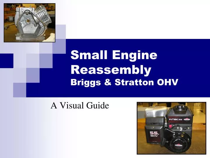
Small Engine Reassembly Briggs & Stratton OHV. A Visual Guide. Objectives:. Reassemble an engine following concise steps and detailed notes taken by the student. Utilize proper tool techniques. Reinforce lecture-based theoretical discussions.

E N D
Small Engine ReassemblyBriggs & Stratton OHV A Visual Guide
Objectives: • Reassemble an engine following concise steps and detailed notes taken by the student. • Utilize proper tool techniques. • Reinforce lecture-based theoretical discussions. • Utilize and reference engine standards with appropriate engine manuals.
Procedure Notes: • Follow the reassembly steps precisely. • Be sure to reference notes and sketches you created during engine disassembly. • Your engine may not be exactly like the engine in this presentation. Even if your Briggs & Stratton OHV engine is not exactly like the model used in this presentation, many of the procedures will be the same. • Use reassembly grease on all internal parts and follow all specifications!
Pre-Assembly Cleaning Clean all internal parts in the parts cleaning cabinets. Remove excess solvent with compressed air. Eye protection and chemical resistant gloves are required.
Step 1: Install the Crankshaft Pre-operation grease Reminder: Tapered end to the front of the engine.
Step 2: Reassemble the Piston Rings and Connecting Rod Reminder: The rings must be replaced correctly. Review your sketch of connecting rod and piston ring orientation.
Step 2: Reassemble the Piston Rings and Connecting Rod wrist pin clips Connecting rod & piston orientation. Arrow on piston and MAG abbreviation to the magneto side of the engine.
Step 3: Install the Piston and Connecting Rod in the Cylinder Reminder: Clean and coat cylinder wall with lubricant. Use piston ring compressor. Install in the correct orientation.
Step 3: Install the Piston and Connecting Rod in the Cylinder Use your thumbs or the handle of a mallet to gently insert the piston assembly. Rotate the crankshaft to prevent it from striking the connecting rod during reassembly.
Step 4: Replace Connecting Rod Cap Short screw and oil splash away from cylinder Arrow toward cylinder Reminder: Lubricate interior of rod cap and connecting rod. Replace cap and rod in the correct direction. Replace oil splash and rod cap lock. Torquescrews properly.
Step 5: Replace Tappets Note: Lubricate each tappet
Step 6: Replace Cam Gear Reminder: Make sure journal is secure. Line up timing marks. Lubricate all bearing surfaces.
Step 7: Install Crankcase Cover Reminder: Use correct gasket. Tighten bolts in correct sequence by skipping across the cover. Replace oil seal if needed. Adjust end play if needed.
Step 8: Install Flywheel Install flywheel and key. Torque flywheel nut using a strap wrench and ft.lb. torque wrench. Install Starter Cup and Nut
Installing Cylinder Head & Adjusting Overhead Valves Return to your measurement sheets in Chapter 9 to record your measurements.
Step 9: Insert Valves Into Head Exhaust valve guide rises Insert valves from the bottom of the head, while using your thumbs to lock the valve retainer. Oil seal on intake valve
Step 10: Install the Cylinder Head Reminder: Install head gasket first. Torque head bolts in a crisscross pattern.
Step 11: Install Pushrods & Valve Wear Plates Valve Wear Plates Pushrod
Step 12: Align Rocker Arms with Push Rods & Valve Wear Plates Reminder: Use the rocker arm as a fulcrum to slightly compress each valve spring in order to slide its opposite end on top of the push rod.
Step 13: Prepare the Cylinder for Valve Adjustment Reminder: Rotate piston to TDC compression. Use a screwdriver in the sparkplug opening as a guide or align the PTO keyway to the cylinder. Now rotate the flywheel clockwise until the magnet points straight up. This disengages the compression release on the camshaft.
Step 14: Check Valve Clearance Reminder: According to specification, insert a flat feeler gauge between the rocker arm and valve wear plate. Make adjustments if out of gap tolerance.
Step 15: Adjusting Valve Clearance 1. Insert feeler gauge 2. Loosen locking screw, while holding adjustment nut. 3. Adjust clearance with the adjustment nut. 4. Hold adjustment nut and lock rocker arm.
Step 16: Replace Valve Cover Note: Don’t forget gasket. Short bolt to the top.
Step 17: Install Armature Note: Thread kill wire through port in block. Bolt armature to block. Adjust armature air gap with shim or business card.
Step 18: Insert Heat Shield Note: One screw only
Step 19: Replace Linkage Plate Governor Arm Insert Kill Wire Carburetor Linkage 4 Bolts Reminder: Refer to your drawings to ensure all linkage is correctly assembled.
Step 20: Replace Carburetor Attach spring & linkage to carburetor Insert both gaskets & spacer.
Step 21: Reset Governor (IMPORTANT) Confirm that throttle butterfly is open completely Set throttle to full Reminder: Ensure that all linkage travels freely.
Step 21: Reset Governor (IMPORTANT) Procedure: Use a 1/4” nut driver and 3/8”. Rotate governor shaft counter clockwise until it stops (do not force). Tighten governor arm lock with 3/8” wrench.
Step 23: Replace Blower Housing Note: Linkage plate flange mounts with the blower housing top. Weave the blower housing over, under, and over.
Step 24: Replace Muffler Note: Include gasket. #30 star tool required. Replace muffler guard. One bolt at rear of muffler and four screws at front.
Step 25: Replace Fuel Tank Note: Replace fuel line. Four bolts front and back.
Step 26: Replace Throttle & Fuel Valve Cover Plate Note: Fuel valve must be in off position. Throttle must be at half.
Step 27: Replace Air Cleaner Mounting Plate & Gasket Filter & Cover
Steps 28-29: • Fill Crankcase with clean oil. • Fill fuel tank 1/3 full with gasoline. • Be sure to add gasoline, not any other fuels.
Step 30: Start and Run Engine Reminder: Only while instructor is present. Use engine stand and vice. Turn run switch “ON” and set throttle to 1/2. No starting fluid should be needed.
Step 31: Adjust Carburetor & Take Measurements Let engine operate for approx. 5 min. Full Throttle RPM & Carburetor Adjustment Temperature Readings
Step 32: Remove Fuel & Lubricant Place fuel and lubricant into their appropriate containers.
Reassembly Wrap-Up • Place a piece of tape on your engine that has your name as well as a report of how the engine ran. • Return engine to storage area. • Inventory and clean all tools in your assigned box. • Clean and return your engine storage bin to its storage area. • Clean and straighten your area.