Download
1 / 26
260 likes | 273 Views
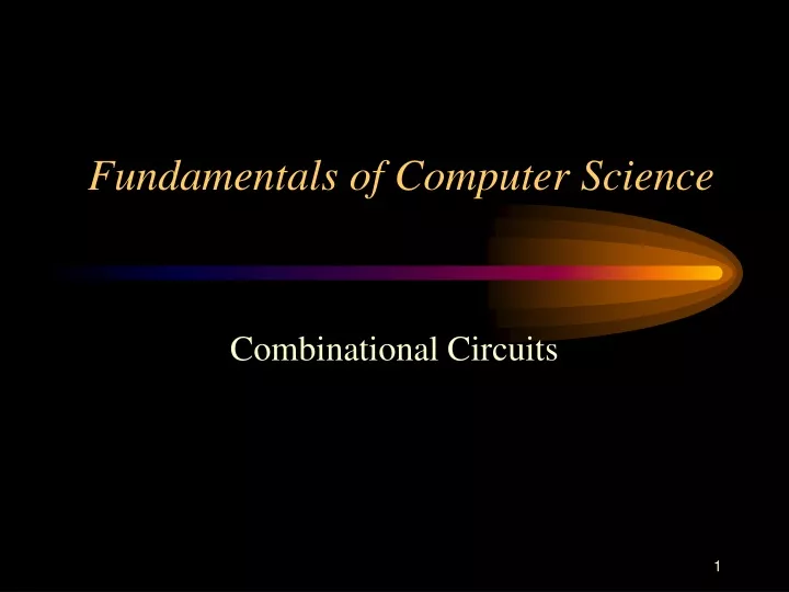
Fundamentals of Computer Science. Combinational Circuits. What is a Combinational Circuit?. Logic circuits for digital systems may be classified as either combinational or sequential .

E N D
Fundamentals of Computer Science Combinational Circuits
What is a Combinational Circuit? • Logic circuits for digital systems may be classified as either combinational or sequential. • A combinational circuit consists of logic gates whose output(s) at any time are based exclusively on the values of external inputs. Combinational Circuit inputs . . . . . . outputs
What is a Sequential Circuit? • A sequential circuit consists of logic gates whose output(s) at any time are based on the values of external input(s) and internally generated input(s). • Sequential circuits are used to implement memory elements. Sequential Circuit inputs . . . . outputs
Predefined Circuits • In programming there are certain functions that are so commonly used across different software systems that they are packaged in libraries of routines that are included with program translators. In this way programmers do not constantly have to “reinvent the wheel”. • In hardware design there are certain circuits that are so commonly used across different hardware systems that they are manufactured in advanced and used as needed as building blocks in larger hardware systems. We will look at several of these circuits in this section.
Multiplexors A multiplexor is a combinational circuit that selects binary information from one of many lines (D) and directs the information to a single output line. The signal selected is determined by a set of input variables called selectors (S). D0 4-to-1 Multiplexor D1 Y D2 D3 S1 S0
Demultiplexors • A demultiplexor is a combinational circuit that routs binary information from a single data line and directs the information to one of several output lines. The output line is determined by a set of input variables called selectors (S). • A demultiplexor doubles as a decoder with enable. 1-to-4 Demultiplexor D0 D1 Enable / Data D2 D3 S1 S0
Implementation of 1-to-4 Line Demultiplexor S1 S0 D3 D2 D1 D0 0 0 0 0 0 E 0 1 0 0 E 0 1 0 0 E 0 0 1 1 E 0 0 0
Decoder • A decoder is a combinational circuit that converts binary information from n coded inputs to a maximum of 2n unique outputs. 3-to-8 Decoder D0 D1 D2 A0 D3 A1 D4 A2 D5 D6 D7
Encoder • A encoder is a combinational circuit that performs the inverse operation of a decoder. It will have 2n or fewer input lines and n outputs. • At any given time only one of the input lines will be high. If multiple inputs are high, the circuit will perform improperly. D0 8-to-3 Encoder D1 D2 A0 D3 A1 D4 A2 D5 D6 D7
Octal to Binary Encoder Truth table for an octal to binary encoder.
Priority Encoder • A priority encoder allows for the possibility that multiple inputs will be high simultaneously. • Each input is assigned a fixed priority, if multiple inputs are high simultaneously the one with the highest priority will determine the output of the encoder • Truth table for an base four to binary encoder with a valid output indicator, V. • This is an example of a condensed truth table.
Priority Encoder Simplification of a base four to binary priority encoder.
Full Adder • A full adder is a combinational circuit that sums three 1-bit binary numbers. • Full adders are typically connected in series via their CIN and COUT lines in order to sum two multi-digit binary numbers. • C stands for carry. A0 Full Adder S0 B0 COUT CIN
4-Bit Ripple Carry Adder • Ripple Carry Adders suffer from propagation delay. • This is a major problem if the adder is large.
4-Bit Carry Lookahead Adder Carry Lookahead Adders are used to reduce the amount of propagation delay during addition of large values.
2’s Complement Representation • Most modern computers use 2’s complement representation to store signed integers. • The high-order bit of an integer stored in 2’s complement representation will contain a 0 if the number is positive and a 1 if the number is negative. • By taking the 2’s complement of an integer you are effectively multiplying the number by -1. • The 2’s complement of a positive integer results in its negative representation. • The 2’s complement of a negative integer results in its absolute value.
2’s Complement Representation • Taking the 2’s complement of an integer is a 2-step process. • Step 1 - Flip all the bits in the number (0’s become 1’s and 1’s become 0’s). This is also known as taking the 1’s complement of the number. • Step 2 - Add 1 to the 1’s complement representation of the number). • In the process of adding 1, any carry out of the high-order position is lost. This is normal and not a problem in the world of computer arithmetic.
2’s Complement Representation • Assume we are storing a positive 9 in a one-byte (8-bit field) using 2’s complement representation. In binary it would appear as 00001001. • Now, take the 2’s complement of the number. • Step 1 - flip the bits. 11110110 • Step 2 - add 1. + 1 11110111 • The result, 11110111, is the 2’s complement representation of -9. • If we were to take the 2’s complement of 11110111 (-9), we would get 00001001 (+9).
2’s Complement Arithmetic • To confirm that 11110111 really does represent -9, we should be able to add it to +9 and get a result of 0. Remember we are doing binary addition: 1 + 1 = 10. 11110111 (-9) + 00001001 (+9) 00000000 (0) • As pointed out earlier, a carry out of the high-order position is lost.
Adder-Subtractor Circuit • Most ALUs do not have a separate set of integer subtraction circuitry. Instead, subtraction is performed in terms of addition. For example, A - B would be performed as A + (-B). If S is high B is subtracted from A. If S is low B is added to A.
Carry-Overflow Detection • If the carry out of the high-order bit (C n) is different from the carry into the high-order bit (C n-1) then overflow (V) has occurred. • Overflow detection is significant when doing arithmetic on signed numbers. • C is equal to the value of C n. • Carry detection is significant when doing arithmetic on unsigned numbers.