Download
1 / 15
160 likes | 312 Views
802.11ah network outdoor deployment issues. Authors:. Date: 2011-Nov-03. Abstract. This presentation discusses two 802.11ah outdoor deployment issues, limited coverage range and hidden node issue, due to restricted transmission power and low mobile antenna efficiency.

E N D
802.11ah network outdoor deployment issues Authors: • Date:2011-Nov-03 Fei Tong,Les Smith, CSR
Abstract • This presentation discusses two 802.11ah outdoor deployment issues, limited coverage range and hidden node issue, due to restricted transmission power and low mobile antenna efficiency. • The authors propose to define power classes and adopt multiple AP network topology in 11ah specification. Fei Tong,Les Smith, CSR
Achieving outdoor coverage • Outdoor coverage requirement in 11ah • Support up to 1km with 100kbps data rate • The requirement comes from the characteristic of applications • Geographic distribution of sensors or mobile stations • Limiting factors for coverage (for a given data rate) • Signal bandwidth (narrow band transmission can reach far, only consider minimal signal bandwidth 1MHz in this discussion) • Propagation environment • Transmission power • Antenna gain and radiation pattern Fei Tong,Les Smith, CSR
Tx Power constraints • Wide range of maximal Tx power constrains in regions • 3 mW or 10 mW depending on channels in South Korea • 5 mW or 10 mW depending on channels in China • 1 mW, 20 mW or 250 mW depending on channels in Japan • 25 mW in Europe • 1 W in US Fei Tong,Les Smith, CSR
Mobile station antenna design constraints • Low frequency mobile antenna efficiency is low • Small low-frequency antennas are often much lower than 0dB • It is a non-trivial exercise to design relatively small antennas with fractional bandwidths of > 7% • Space within mobile station is usually very limited and internal components affect the shape of the radiation pattern • Losses due to coexistence with cellular transceiver • Provide protection from relative high power cellular uplink transmission • Either from Rx front-end protection circuitry • Or adding a switch in the 11ah antenna path Fei Tong,Les Smith, CSR
Realistic antenna gain • Best case antenna gain • Vertically polarized, gain +2dB, omni-directional for AP • Vertically polarized, gain –3dB, omni-directional for hand-held mobile station • Antenna gain variation due to antenna orientation • For antennas in mobile hand-held applications, the radiation pattern is essentially omni-directional in one plane only • As the user moves it around, the relative antenna orientation would result a gain variations of 20dB or more Fei Tong,Les Smith, CSR
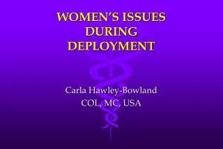
Study the received SNR at the cell edge • Downlink link budget Assumptions • Carrier frequency 900MHz • Tx power level • 1, 3, 5, 10, 20, 25, 250, 1000 mW • Best case antenna gain +2dB at AP, -3dB at mobile station • Noise figure at mobile station 7 dB • Noise floor -114 dBmW/MHz • Propagation path loss • Outdoor macro path loss model • No shadowing loss Fei Tong,Les Smith, CSR
Downlink SNR at different distance Fei Tong,Les Smith, CSR
Discussion on achieving the coverage • If PHY is simply down-clocked by 10 from 11ac PHY • Minimal data rate will be 325kbps requiring at least 1.5dB SNR • Adding 8 dB shadowing margin and 3dB implementation loss, required cell edge SNR to achieve minimal data rate will be 12.5dB • Uplink and downlink link budget are not symmetric • Uplink is 5 dB better than downlink assuming maximal ERP at the mobile station • Uplink received power: Max ERP – PL + Gap • Downlink received power: Max ERP – PL + Gsta • Can not achieve 1km coverage with a single central AP in all regions due to Tx power constrains Fei Tong,Les Smith, CSR
Hidden node issues • Wide range outdoor deployment may result in high percentage hidden nodes • Low antenna height and antenna gain on mobile stations • Random mobile antenna orientations • Averagely longer propagation distance between stations than from AP to mobile stations, especially when coverage is wide • Hearing other stations’ transmission is critical for carrier sense • Collision avoidance relies on hearing transmission (at least the preamble) from other stations • RTS/CTS may not be effective when the percentage of hidden nodes is high (collisions on RTS) Fei Tong,Les Smith, CSR
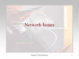
Study the percentage of hidden nodes • Carrier frequency 900MHz • Tx power level 25 mW • Antenna gain -3dB at mobile station, • Uniform distributed (0-20dB) antenna orientation loss • Noise figure at mobile station 7 dB • Noise floor -114 dBmW/MHz • Sensitivity for STF detection (-1.5 dB SNR) • Outdoor macro path loss model • 8 dB log-normal shadowing loss • Coverage radius, 250m, 500m and 1000m Fei Tong,Les Smith, CSR
CDF of percentage of hidden nodes Fei Tong,Les Smith, CSR
Discussion on hidden nodes issue • Mainly due to widely scattering of stations • For 1km radius, on average stations cannot hear 70% of other stations; • For 250m radius, stations can hear 90% of other stations • May result in more collision of transmissions and power consumption due to the prolonged transmission attempt Fei Tong,Les Smith, CSR
Possible solutions • Define device power classes/capability • Easy to identify devices conforming to regional requirements • Enable AP to manage devices with different max Tx power • Allow multiple APs network topology • Enable lower power class device supporting wider coverage • Study suitability of existing ESS model • Mitigation techniques required for overlapping BSS’s • High percentage of hidden nodes within the network • May require coordination between APs using in-band or out-band link Fei Tong,Les Smith, CSR
References • Minho Cheong, IEEE 802.11-11/0905r4, TGah Functional Requirements and Evaluation Methodology • Rolf de Vegt, IEEE 802.11-11/1296r3, Potential Channelization for 802.11ah • Ron Porat and SK Yong, IEEE 802.11-11/0968r1, TGah Channel Model Fei Tong,Les Smith, CSR