Download
1 / 14
140 likes | 260 Views
Modeling Agent Mobility with UML Sequence Diagram. Mario Kusek, Gordan Jezic Department of Telecommunications Faculty of Electrical Engineering and Computing University of Zagreb, CROATIA Agent-Oriented Software Engineering TFG, AL3 February 28 th – March 2 nd , 200 5 , Ljubljana, Slovenia.

E N D
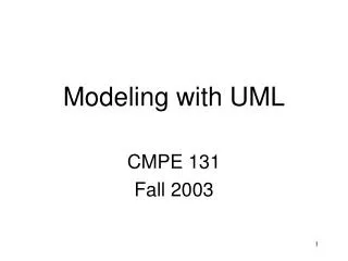
Modeling Agent Mobility with UML Sequence Diagram Mario Kusek, Gordan Jezic Department of Telecommunications Faculty of Electrical Engineering and Computing University of Zagreb, CROATIA Agent-Oriented Software Engineering TFG, AL3 February 28th – March 2nd, 2005, Ljubljana, Slovenia AOSE TFG, AL3
Outline • Motivation • Related work • Proposed diagrams • Case study • Conclusions AOSE TFG, AL3
Motivation • Existing diagrams • Weak representation of agent moving and execution path • Does not represent mobility in Sequence Diagram • Proposition for modeling • Agent creation, • Mobility path, and • Current location AOSE TFG, AL3
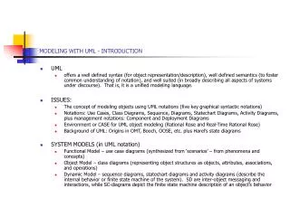
AUML – Deployment and Activity Diagram • Captures why and where agents move • Activity nodes model plan • Transitions model events • Mobility is indicated as a note “when: condition” on the transition that leads to the end point • Deployment diagram model combined with activity gives overall picture • Specific cases must be extracted from diagrams AOSE TFG, AL3
Extending Activity Diagrams to Model Mobile Systems • Introduced concepts of • location, • mobile object, • mobile location, • move action and • clone action • Two notations of mobility in Activity Diagrams • responsibility centered • who is performing an action • location centered • where an action is performed, and how activities change this relation AOSE TFG, AL3
Modelling Mobile Agent Applications in UML 2.0 Activity Diagrams • Stereotype <<Host>> in swimlane represents location • Agent moving from location “host1” to “host2” is represented by using “Go” • Agent communication and cloning can be represented by subactivities AOSE TFG, AL3
Agent Modeling Language (AML) • Defines metaclasses used to model structural and behavioural aspects of entity mobility • Dependency relationship with the stereotype <<move>> • MobilityAction for modeling mobility action • MoveAction for modeling removal of the entity from its current hosting location AOSE TFG, AL3
Stereotyped Mobility Diagram • Similar to “Sequence Diagrams for Mobility “ • In the case of large number of nodes, the diagram is useless AOSE TFG, AL3
Swimlaned Mobility Diagram • Idea from “Modelling Mobile Agent Applications in UML 2.0 Activity Diagrams” • Clear representation of mobility • Needs less space than stereotyped diagram • In the case of large number of nodes it is also useless AOSE TFG, AL3
State Representation Mobility Diagram • Good for large number of nodes • Poorer representation of mobility • Consumes more space in vertical representation • Candidate for implementing mobility in Sniffer agent (in JADE) AOSE TFG, AL3
Frame Fragment Mobility Diagram • Good for large number of nodes • Mobility is more clearer • Occupied space is smaller • In some cases it is not possible to order agents in a way that one frame fragment can represent agents at the same node AOSE TFG, AL3
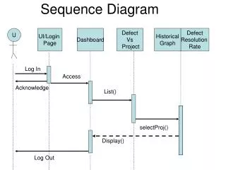
Case study: Simple price searcher AOSE TFG, AL3
Stereotyped Mobility Diagram AOSE TFG, AL3
Conclusions • Four variants of modeling agent mobility based on UML Sequence Diagram notations are proposed • Stereotyped Mobility Diagram • For small number of nodes • Clear representation of agent execution and mobility path • Swimlaned Mobility Diagram • For small number of nodes • Needs less space than Stereotyped Mobility Diagram • State Representation Mobility Diagram • Good for large number of nodes • Representation of agent execution and mobility path not so clear • Frame Fragment Mobility Diagram • Good for large number of nodes • Needs less space than State Representation Mobility Diagram • Not always possible to use it AOSE TFG, AL3