Download
1 / 37
390 likes | 595 Views
Review on Graphics Basics. Outline. Polygon rendering pipeline Affine transformations Projective transformations Lighting and shading From vertices to fragments. Outline. Polygon rendering pipeline Affine transformations Projective transformations Lighting and shading

E N D
Outline • Polygon rendering pipeline • Affine transformations • Projective transformations • Lighting and shading • From vertices to fragments
Outline • Polygon rendering pipeline • Affine transformations • Projective transformations • Lighting and shading • From vertices to fragments
Polygon Rendering Pipeline • Process objects one at a time in the order they are generated by the application • Pipeline architecture • All steps can be implemented in hardware on the graphics card application program display
Vertex Processing • Much of the work in the pipeline is in converting object representations from one coordinate system to another • Object coordinates • Camera (eye) coordinates • Screen coordinates • Every change of coordinates is equivalent to a matrix transformation • Vertex processor also computes vertex colors
Projection • Projection is the process that combines the 3D viewer with the 3D objects to produce the 2D image • Perspective projections: all projectors meet at the center of projection • Parallel projection: projectors are parallel, center of projection is replaced by a direction of projection
Primitive Assembly Vertices must be collected into geometric objects before clipping and rasterization can take place • Line segments • Polygons • Curves and surfaces
Clipping Just as a real camera cannot “see” the whole world, the virtual camera can only see part of the world or object space • Objects that are not within this volume are said to be clipped out of the scene
Rasterization • If an object is not clipped out, the appropriate pixels in the frame buffer must be assigned colors • Rasterizer produces a set of fragments for each object • Fragments are “potential pixels” • Have a location in frame buffer • Color and depth attributes • Vertex attributes are interpolated over objects by the rasterizer
Fragment Processing • Fragments are processed to determine the color of the corresponding pixel in the frame buffer • Colors can be determined by texture mapping or interpolation of vertex colors • Fragments may be blocked by other fragments closer to the camera • Hidden-surface removal
Outline • Polygon rendering pipeline • Affine transformations • Projective transformations • Lighting and shading • From vertices to fragments
Affine Transformations • Line and parallelism preserving • Affine transformations used in Graphics • Rigid body transformations: rotation, translation • Scaling, shear • Importance in graphics is that we need only transform endpoints of line segments and let implementation draw line segment between the transformed endpoints
Homogeneous Coordinates The homogeneous coordinates form for a three dimensional point [x y z] is given as p =[x’ y’ z’ w] T=[wxwywz w] T We return to a three dimensional point (for w0) by xx’/w yy’/w zz’/w If w=0, the representation is that of a vector Note that homogeneous coordinates replaces points in three dimensions by lines through the origin in four dimensions For w=1, the representation of a point is [x y z 1]
Homogeneous Coordinates and Computer Graphics • Homogeneous coordinates are key to all computer graphics systems • All standard transformations (rotation, translation, scaling) can be implemented with matrix multiplications using 4 x 4 matrices • Hardware pipeline works with 4 dimensional representations
Translation Matrix We can also express translation using a 4 x 4 matrix T in homogeneous coordinates p’=Tp where T = T(dx, dy, dz) = This form is better for implementation because all affine transformations can be expressed this way and multiple transformations can be concatenated together
Rotation (2D) Consider rotation about the origin by q degrees • radius stays the same, angle increases by q x’ = r cos (f + q) y’ = r sin (f + q) x’=x cos q –y sin q y’ = x sin q + y cos q x = r cos f y = r sin f
Rotation about the z axis • Rotation about z axis in three dimensions leaves all points with the same z • Equivalent to rotation in two dimensions in planes of constant z • or in homogeneous coordinates p’=Rz(q)p x’=x cosq –y sin q y’ = x sin q + y cosq z’ =z
Rotation Matrix R = Rz(q) =
Scaling Expand or contract along each axis (fixed point of origin) S = S(sx, sy, sz) = x’=sxx y’=syx z’=szx p’=Sp
Reflection corresponds to negative scale factors sx = -1 sy = 1 original sx = -1 sy = -1 sx = 1 sy = -1
Shear • Helpful to add one more basic transformation • Equivalent to pulling faces in opposite directions
Shear Matrix Consider simple shear along x axis x’ = x + y cot q y’ = y z’ = z H(q) =
Outline • Polygon rendering pipeline • Affine transformations • Projective transformations • Lighting and shading • From vertices to fragments
Affine vs. Projective Transformation • Difference is in the last line of the transformation matrix. • Projective transformation preserves collinearity but not parallelism, length, and angle. • Affine transformation is a special case of the projective transformation. However, it preserves parallelism. Ma= Mp=
Projections and Normalization • The default projection in the eye (camera) frame is orthogonal • For points within the default view volume • Most graphics systems use view normalization • All other views are converted to the default view by transformations that determine the projection matrix • Allows use of the same pipeline for all views xp = x yp = y zp = 0
Homogeneous Coordinate Representation default orthographic projection xp = x yp = y zp = 0 wp = 1 pp = Mp M = In practice, we can letM = Iand set the z term to zero later
Simple Perspective • Center of projection at the origin • Projection plane z = d, d < 0
Perspective Equations Consider top and side views xp = yp = zp = d
Homogeneous Coordinate Form consider q = Mp where M = p = q =
Perspective Division • However w 1, so we must divide by w to return from homogeneous coordinates • This perspective division yields the desired perspective equations • We will consider the corresponding clipping volume with the OpenGL functions xp = yp = zp = d
Outline • Polygon rendering pipeline • Affine transformations • Projective transformations • Lighting and shading • From vertices to fragments
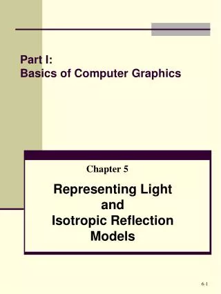
Phong Model For each light source and each color component, the Phong model can be written as I = (a+bd+cd2)-1[ kd Idl· n+ks Is (v· r )a +kaIa] For each color component we add contributions from all sources
Example Only differences in these teapots are the parameters in the modified Phong model
Outline • Polygon rendering pipeline • Affine transformations • Projective transformations • Lighting and shading • From vertices to fragments
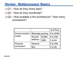
Pipeline Clipping of Polygons • Three dimensions: add front and back clippers • Strategy used in SGI Geometry Engine • Small increase in latency
Scan Conversion and Interpolation C1 C2 C3 specified by glColor or by vertex shading C4 determined by interpolating between C1 and C2 C5 determined by interpolating between C2 and C3 interpolate between C4 and C5 along span C1 C4 C2 scan line C5 span C3
Hidden Surface Removal • z-Buffer Algorithm • Use a buffer called the z or depth buffer to store the depth of the closest object at each pixel found so far • As we render each polygon, compare the depth of each pixel to depth in z buffer • If less, place shade of pixel in color buffer and update z buffer